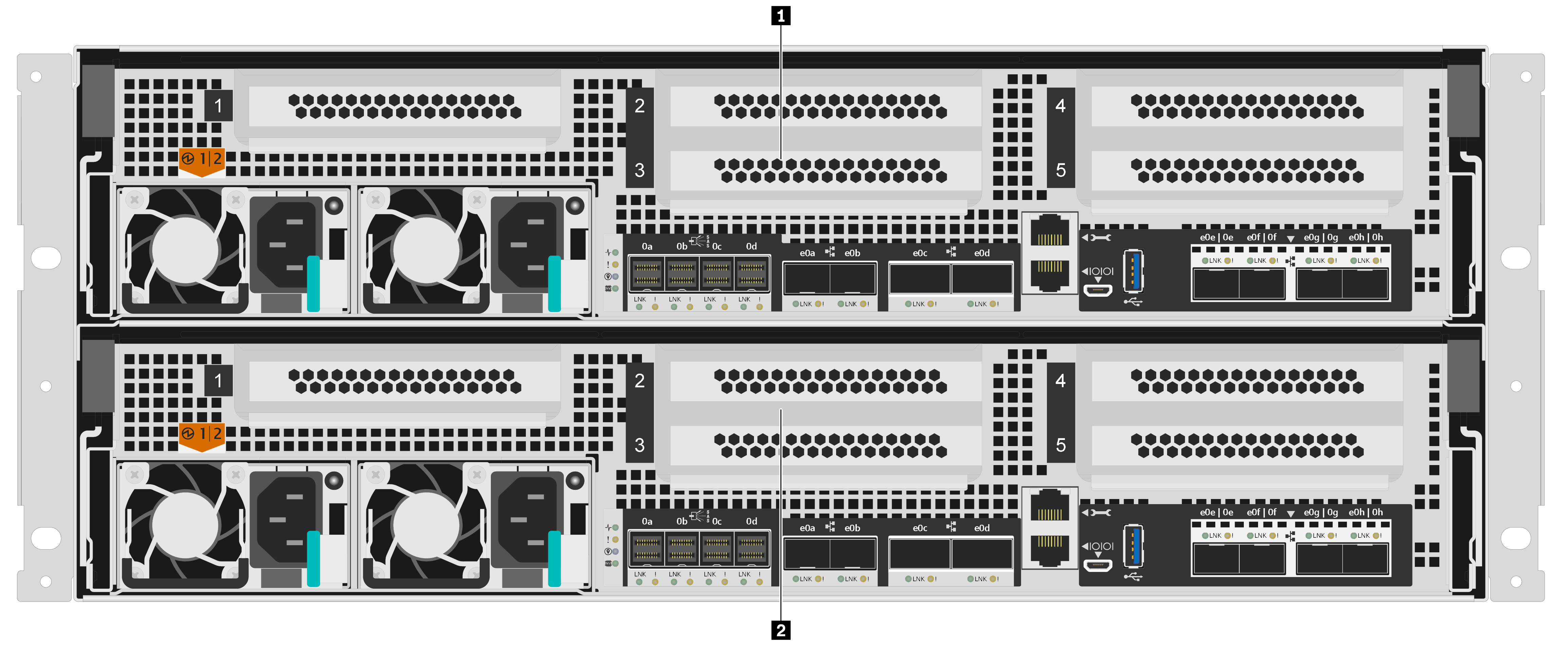
Rear view
The rear view of the storage provides access to the system connectors and components.

| 1 Top controller, node A | 2 Bottom controller, node B |

| 1 PCIe slot 1 (on riser 1) | 2 PCIe slot 2 (on riser 2) |
| 3 PCIe slot 3 (on riser 2) | 4 PCIe slot 4 (on riser 3) |
| 5 PCIe slot 5 (on riser 3) | 6 Power supply 1 |
| 7 Power supply 2 | 8 x4 12 Gb mini-SAS HD (SFF-8644) connectors (4) |
| 9 25 GbE SFP28 connectors (2) | 10 100 GbE QSFP28 connectors (2) |
| 11 1 GbE RJ-45 management port | 12 RJ-45 console port |
| 13 Micro-USB console port | 14 USB Type-A port |
| 15 16 GB Fibre channel SFP+ ports or 25 GbE SFP28 ports (4) |
1 2 3 4 5 PCIe slots
You can find the PCIe slot numbers on the rear of each controller.
6 7 Power supplies
The hot-swap redundant power supplies help you avoid significant interruption to the operation of the system when a power supply fails. Each controller can continue to operate with a single power supply failure.
On each power supply, there are multi-color status LEDs near the power cord connector. For information about the status LEDs, see Rear view LEDs.
8 x4 12 Gb mini-SAS HD (SFF-8644) connectors (4)
Each controller includes four x4 12 Gb SAS ports that are used for connecting SAS based external storage enclosures. Refer to Installation and Cabling Guide for DM120S, DM240S, and DM600S for instructions on how to cable up SAS expansion enclosures. Installation and Cabling Guide for DM120S, DM240S, and DM600S provides details on how many SAS expansion units can be attached per storage stack.
9 25 GbE SFP28 connectors (2)
Each controller includes two 25 Gb ethernet ports that are used to provide node-to-node high availability.
10 100 GbE QSFP28 connectors (2)
Each controller includes two 100 Gb ethernet ports that are used to provide node-to-node clustering or switch node clustering on a DM7100H. On a DM7100F, these ports are used for connecting NVMe-based expansion enclosures.
11 1 GbE RJ-45 management port
The RJ-45 console port connection provides 1 Gb Ethernet connectivity to the node for systems management using the DM Storage Manager.
12 RJ-45 console port
The RJ-45 console port connection provides serial access to the nodes BMC management network device.
13 Micro-USB console port
The Micro-USB console port connection provides serial access to the nodes BMC management network device.
14 USB Type-A port
The USB Type-A port is a Read-Only connection that can be used for ONTAP netboot and system updates.
15 16 GB Fibre channel SFP+ ports or 25 GbE SFP28 ports (4)
16 GB Fibre channel SFP+ ports: The ports require the use of a 16 Gb SFP+ fiber channel transceiver.
25 GbE SFP28 ports: The ports require the use of either a 25 Gb SFP28 transceiver or 25 Gb Direct Attach Copper (DAC) cable.