Install 48U Advanced Rack Extension Kit
See this topic to learn how to install 48U Advanced Rack Extension Kit.
Each unit of rack extension kit comes with additional capacity for up to two 0U PDUs, or one 0U PDU and one manifold, on each side of the rack.
Each rack cabinet supports up to two units of rack extension kit (one to the front and one to the rear side).
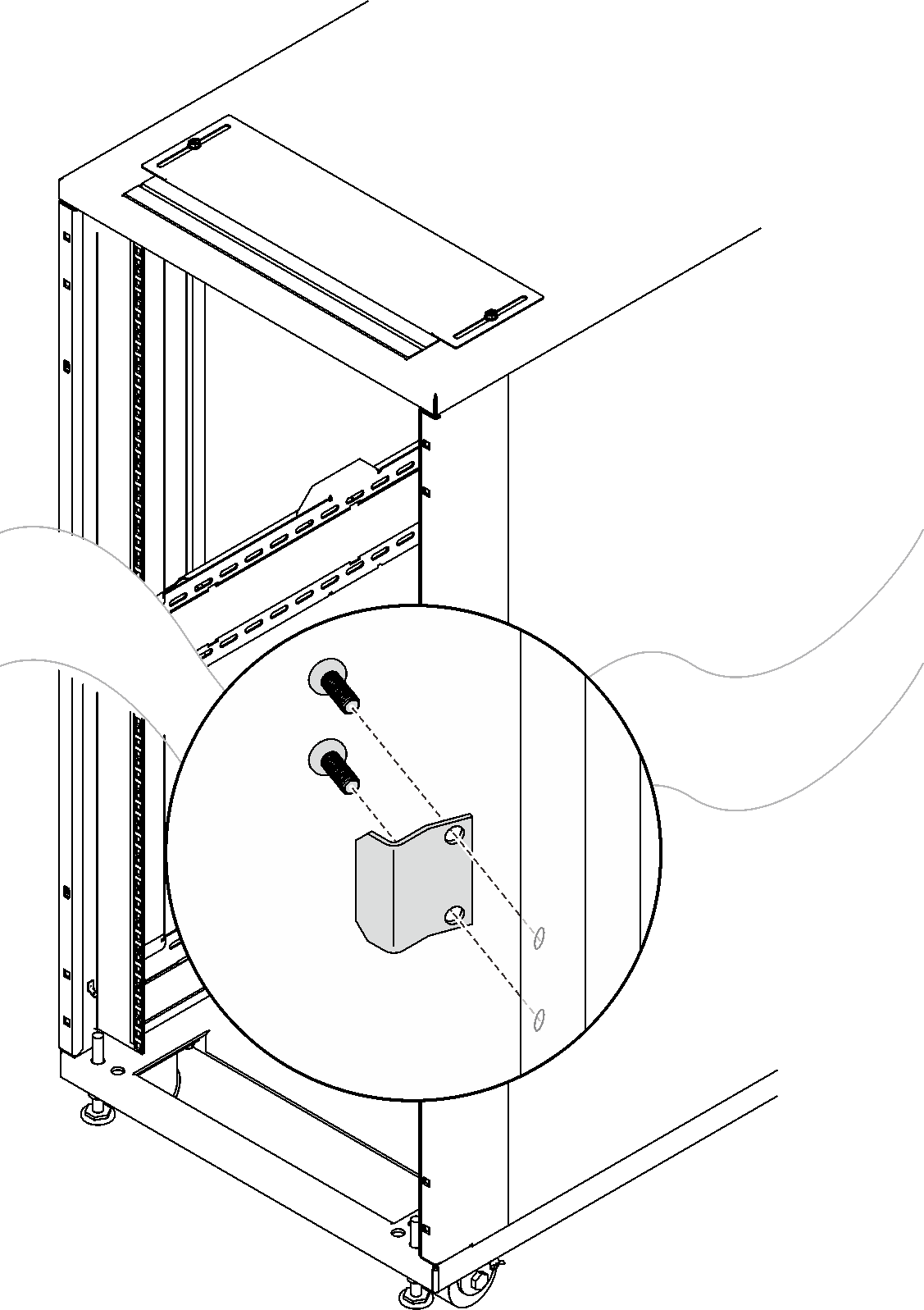
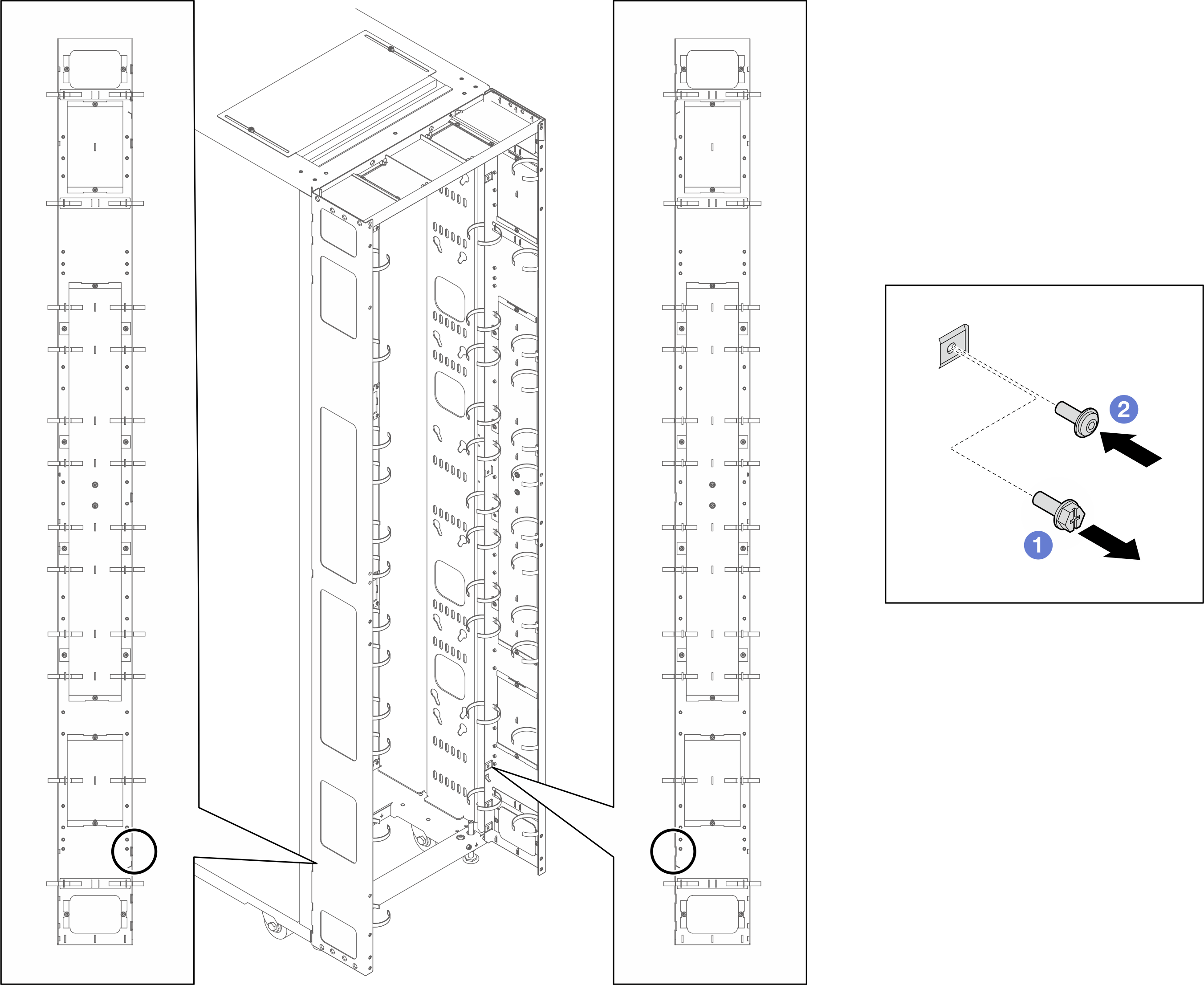
If there is a plan to install baying kit while only one of the adjacent cabinets will be installed with extension, make sure to install the baying kit first (see Install the baying kit). Then, as preparation for this procedure, remove the two screws from the upper and lower part of the cabinet that will be installed with the extension kit, and jump to 5.
Figure 1. Removing screws to prepare for extension installation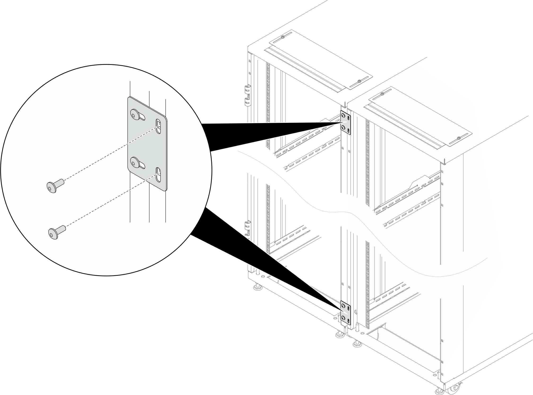
- Required tools
- One tool with plastic blade/scissors to open the packaging
- One rubber hammer to align the extension panels with the side of the rack
- One Screwdriver with No. 3 Phillips bit to tighten the M6 screws (9 in the next bullet point)
- One Nut-driver with holding hex bit 10 mm to tighten the M6 screws (9 in the next bullet point)
- One 2.5 mm Hex bit socket to tighten the M4 screws (13 in the next bullet point)
- One 3 mm Hex bit socket to tighten the M5 screws (PDU/manifold brackets, opening covers on the extension panels)
- One 4 mm Hex bit socket to tighten the M6 screws (3 and 12 in the next bullet point)
- The extension kit comes with a miscellaneous bag, which contains the following components:Figure 2. Parts
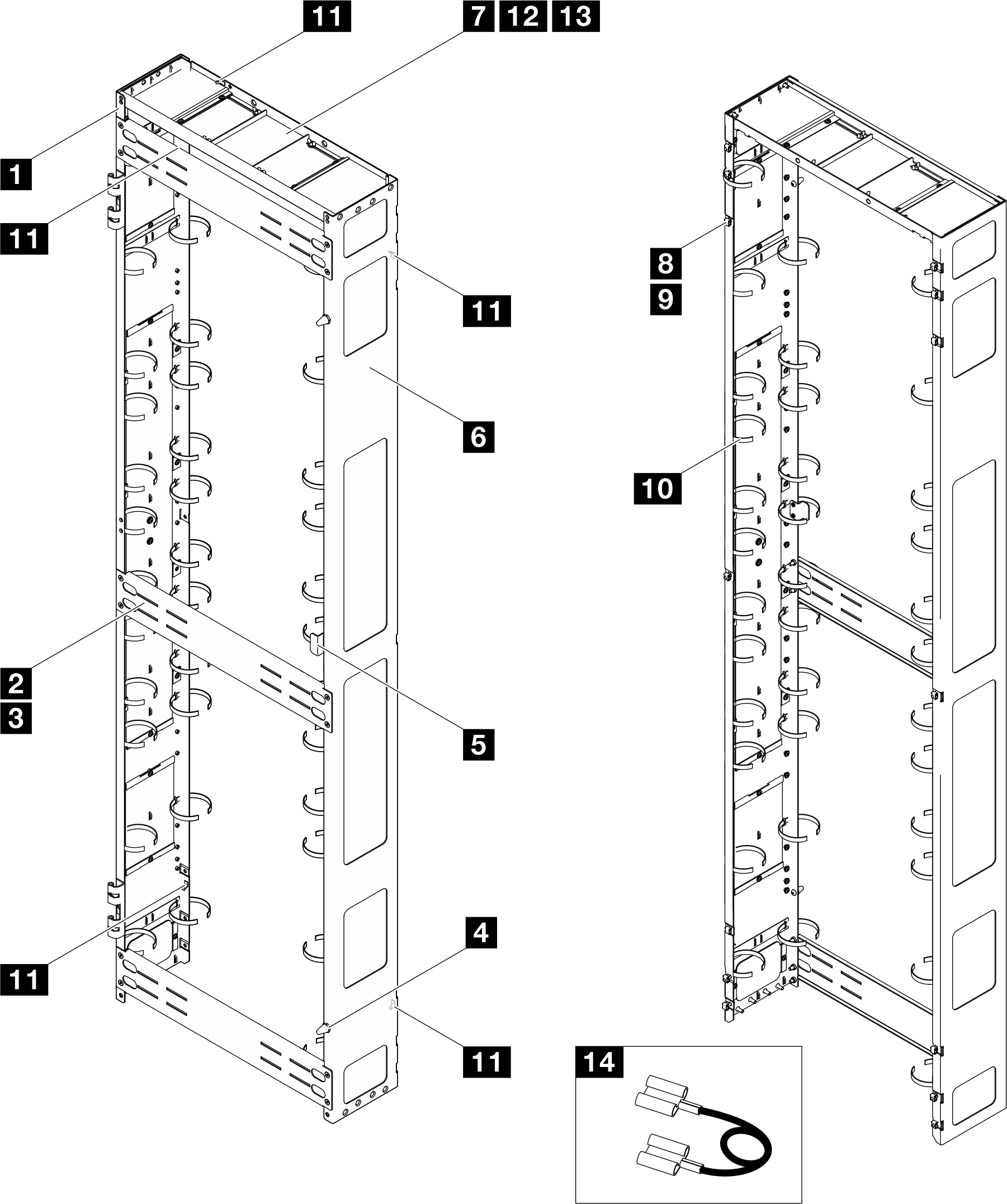
No. Description Quantity No. Description Quantity 1 Left extension panel 1 8 M6 cage nut 14 2 Support bracket 3 9 M6 x 16 mm hex head flange screw 14 3 M6 x 12 mm flat head socket cap screw 12 10 Cable strap module 123 2 4 Doorstop 2 11 Grounding plate 5 5 Door latch 1 12 M6 x 16 mm flat head socket cap screw 2 6 Right extension panel 1 13 M4 x 6 mm flat head socket cap screws 4 7 Extension top cover 1 14 Grounding wire 4 3 - 1 Cable straps are removable, remove the straps from the extension panels if needed.
- 2 Cable straps can be lengthened by connecting two or more straps together.
- 3 Use cable straps to secure PDUs and manifolds prior to shipping.
- 4 Connect one end of the grounding wire to the grounding plate on the extension panel and the other end to the nearest grounding plate on the rack.
Figure 3. Hex Allen wrenches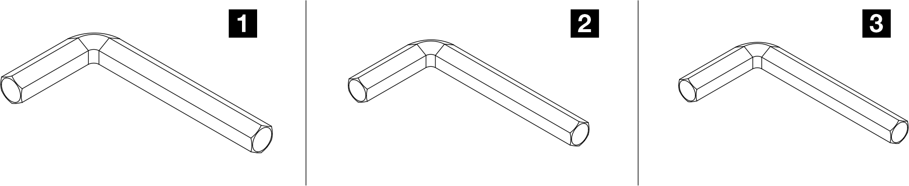
No. Description 1 Hex Allen wrench, 4 mm 2 Hex Allen wrench, 3 mm 3 Hex Allen wrench, 2.5 mm
Procedure
- Remove the door.Figure 4. Removing a door
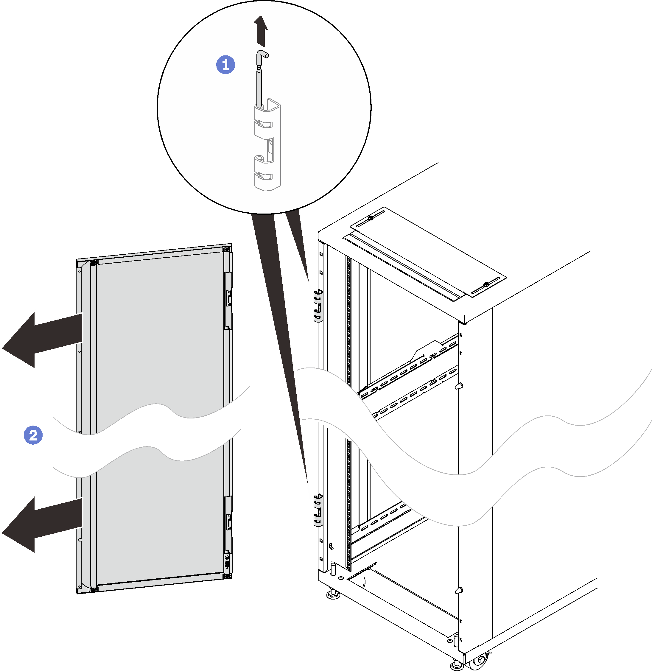
 Hold the door in place, and lift both hinge pins until they lock in the open position so that the door is disengaged.
 Remove the door from the rack cabinet frame.
- Remove the two hinges and the two doorstops.Figure 5. Removing the door hinges and doorstops
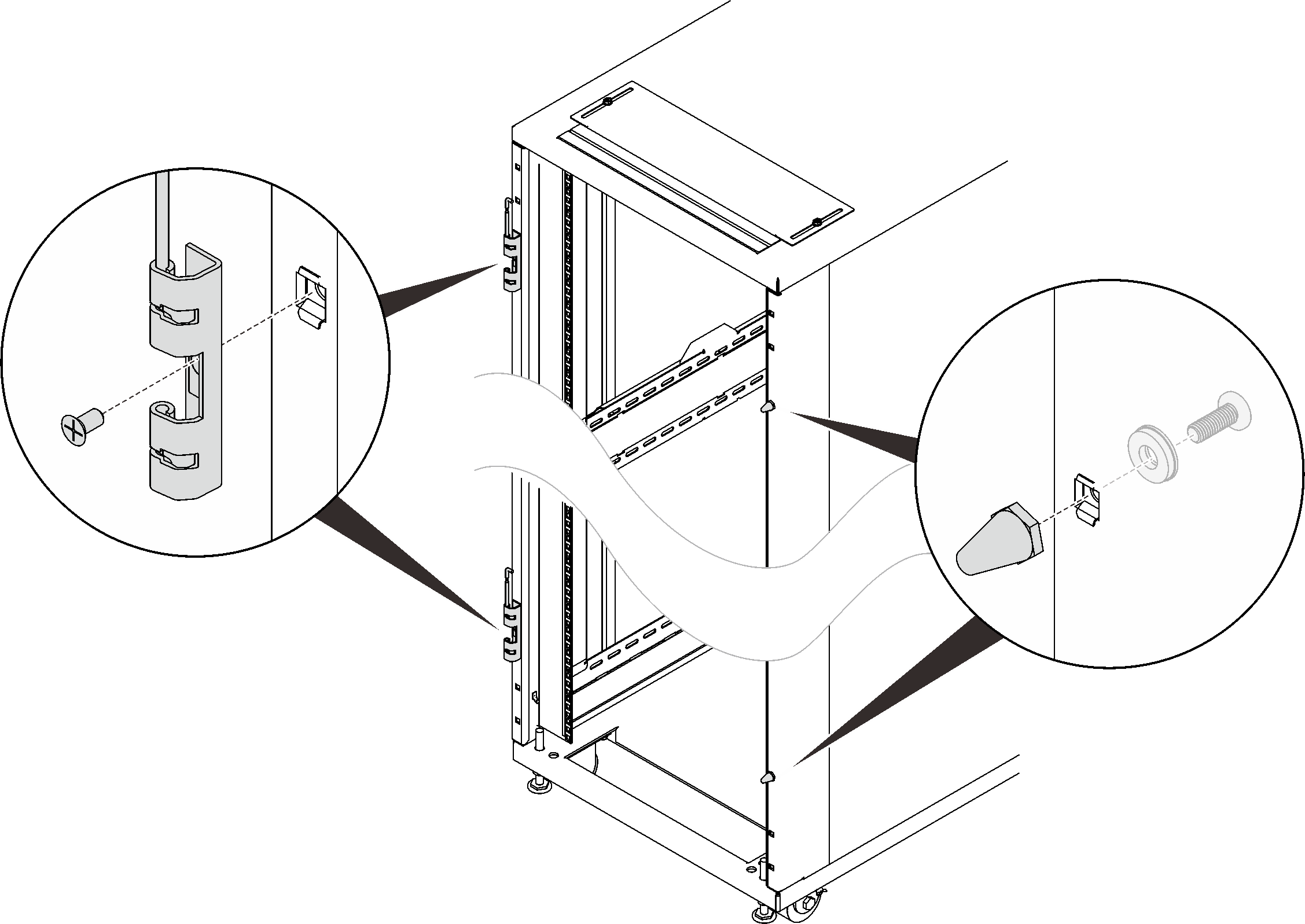
- Remove the door latch.Figure 6. Removing the door latch
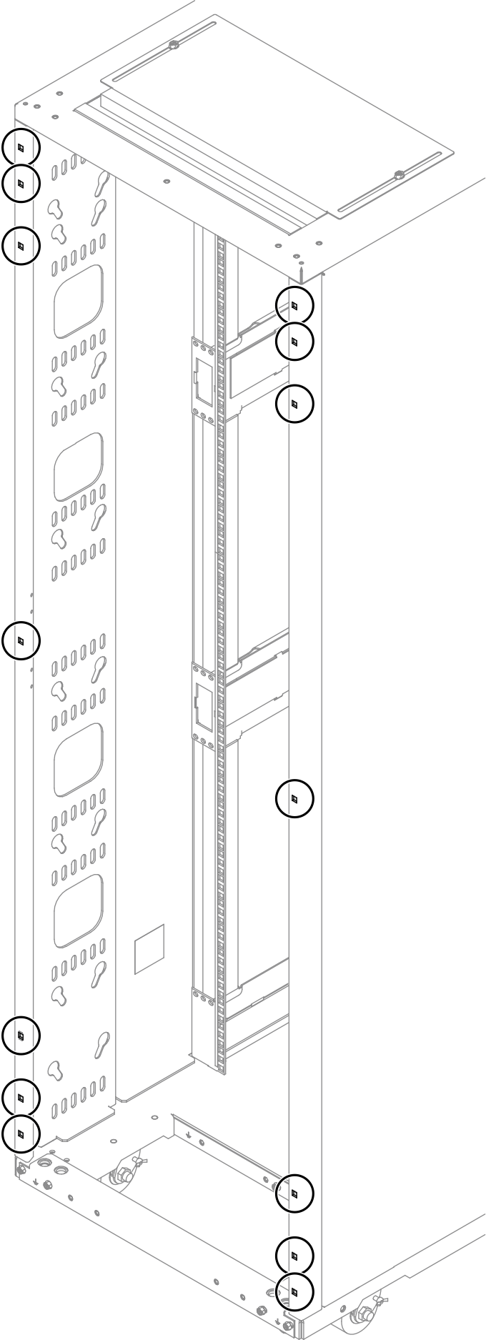
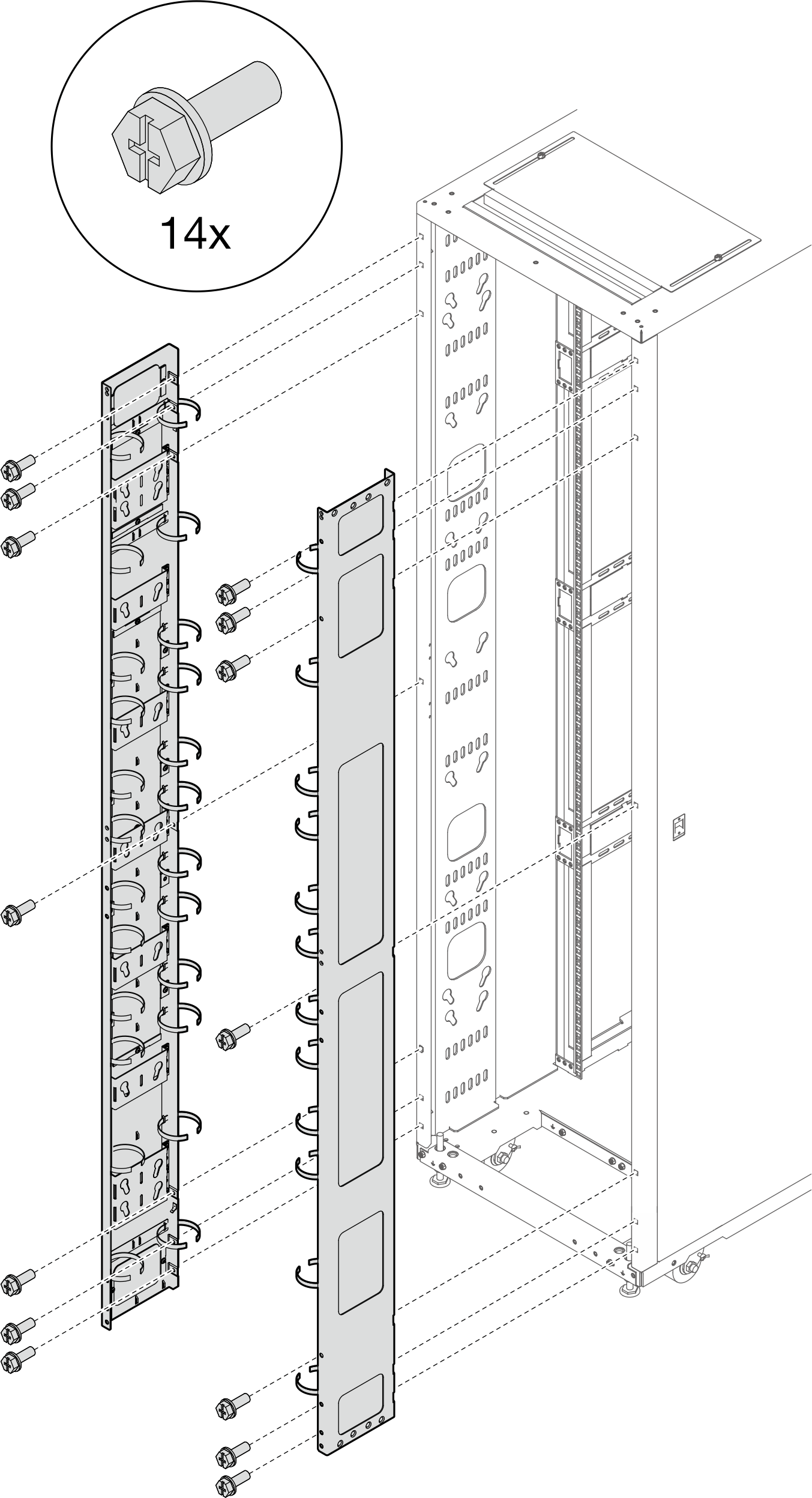
- Install fourteen M6 cage nuts to the rack frame with cage nut insertion tool or a flat-blade screwdriver.Figure 7. Cage nut installation location
 With cage nut insertion toolFigure 8. Installing cage nuts with cage nut insertion tool
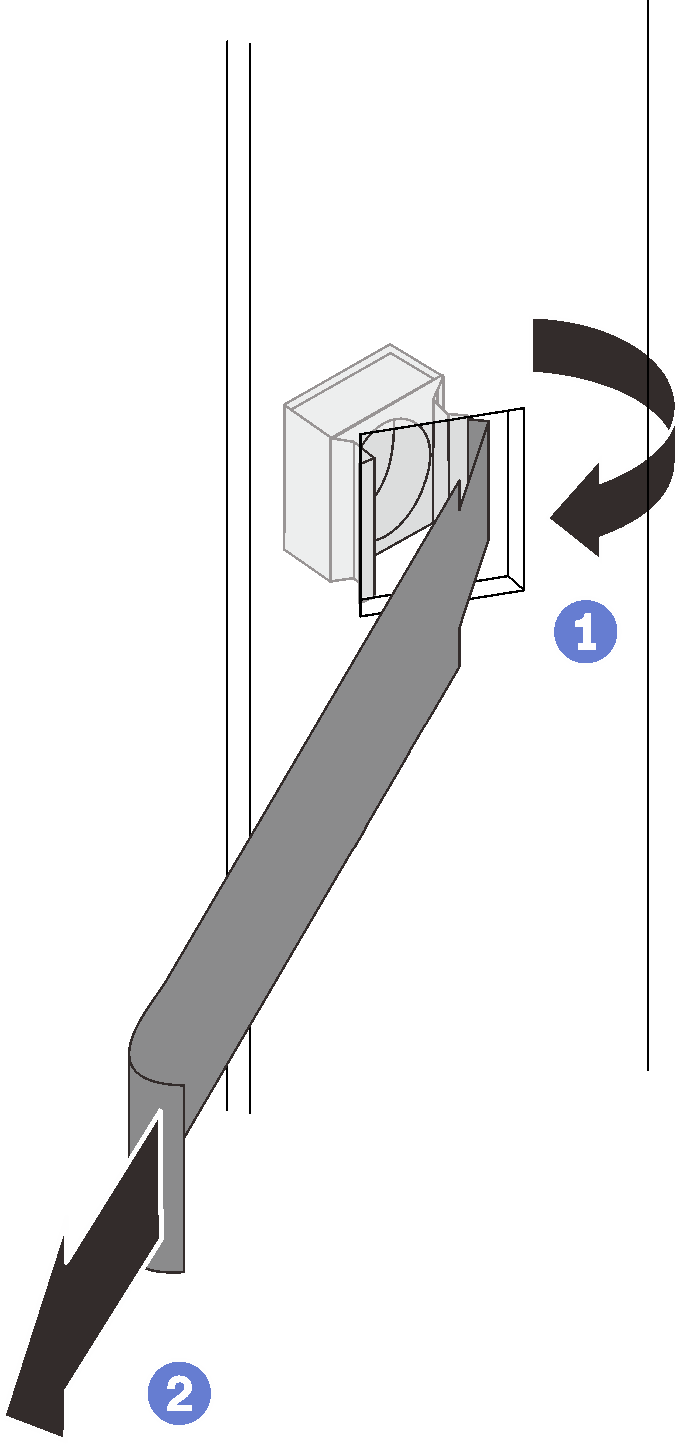
- Insert one edge of the cage nut into the target mounting flange hole, and hook the other edge with the insertion tool through the flange hole.
- Rotate and pull the tool to force the other nut edge into the flange hole, and thus secure the nut.
With flat blade screwdriverFigure 9. Installing cage nuts with flat blade screwdriver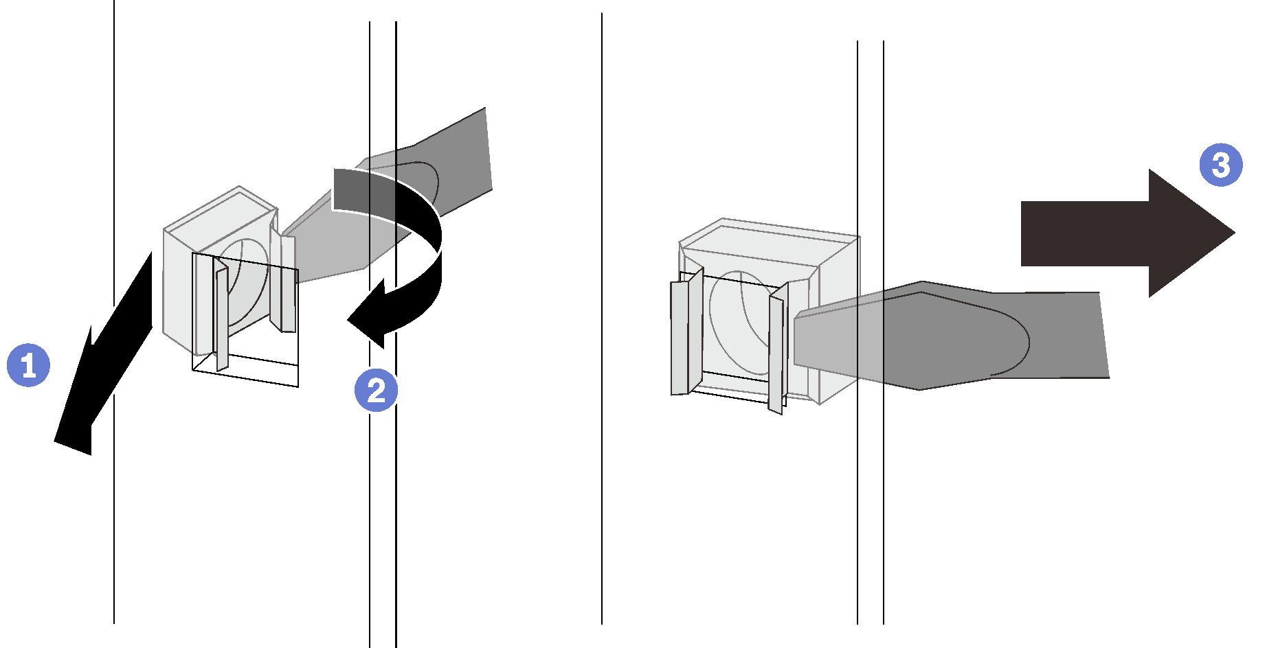
- Insert one edge of the cage nut into the target mounting flange hole.
- Press and compress the other nut edge with a flat-blade screwdriver, and rotate the screwdriver towards the flange hole until the nut edge goes in the hole.
 Release the screwdriver to secure the nut in the mounting flange hole.
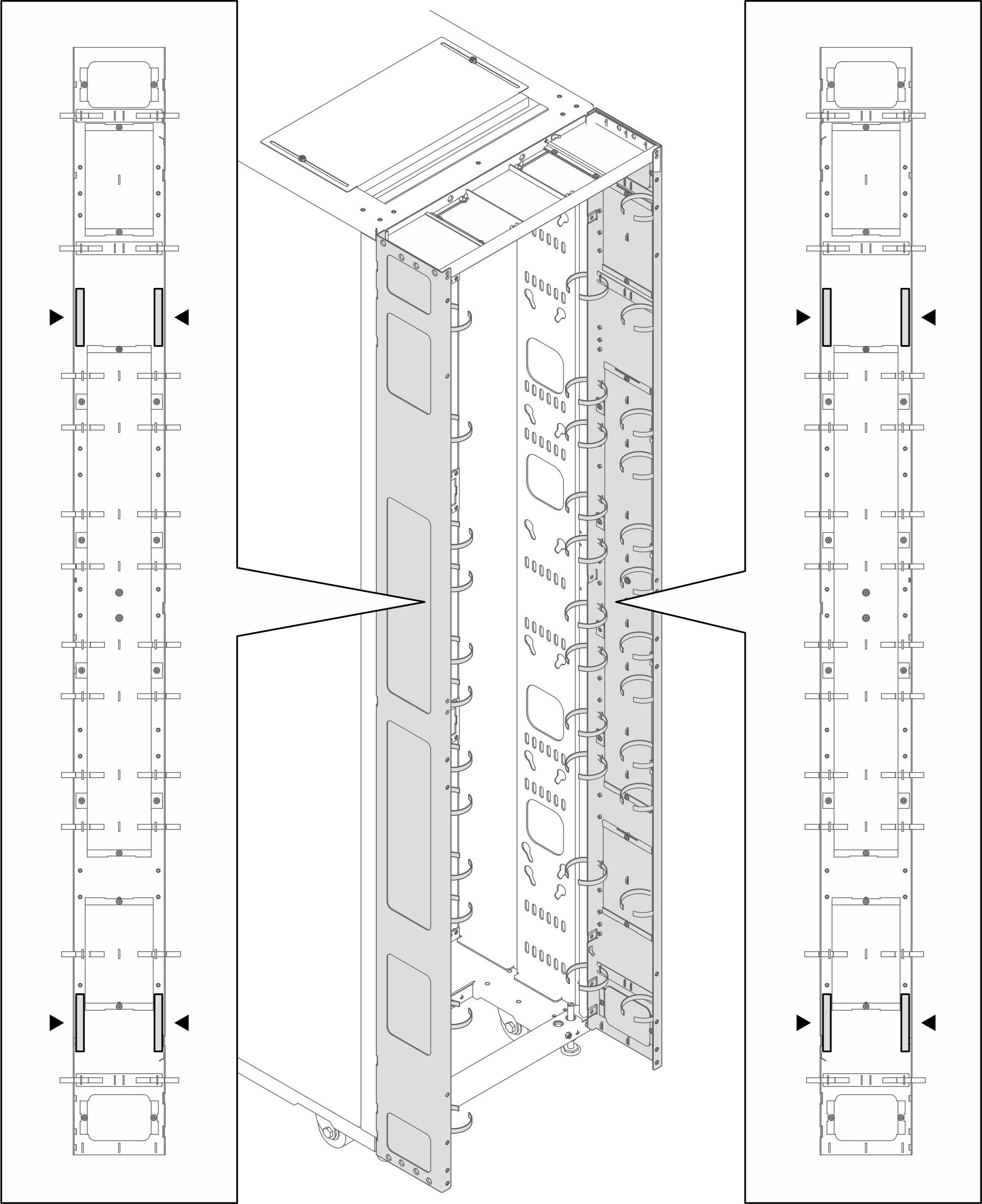
- Tighten the fourteen screws to secure the two extension panels to the rack.NoteIf baying kit has been installed previously, make sure to remove the two screws from top and bottom of the cabinet first. Then, secure the screws through the panel and the baying kit.Figure 10. Installing the extension panels
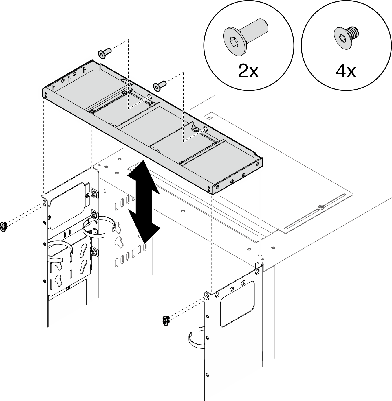
- Align the extension top cover with the screw holes on the extension panels, and secure it with six screws.Figure 11. Installing the extension top cover
- Depending on the requirements, remove the filler(s) from the extension panels to route cables.Figure 12. Removing the filler(s)
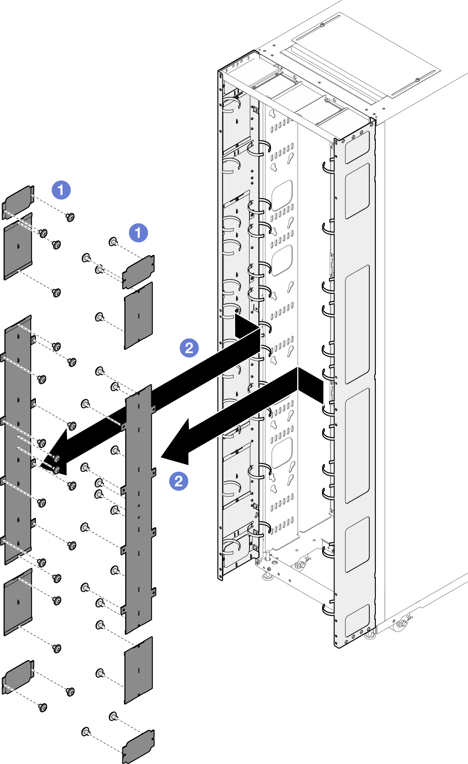
- Loosen the screws that secure the filler to the extension panel.
- Remove the filler.
- If there is a plan to install 0U PDU to the extension panel, complete the following steps.Depending on the requirements, select the corresponding installation procedures.
- Bracket with two keyhole slots (up to two PDUs, or one PDU and one manifold)Note
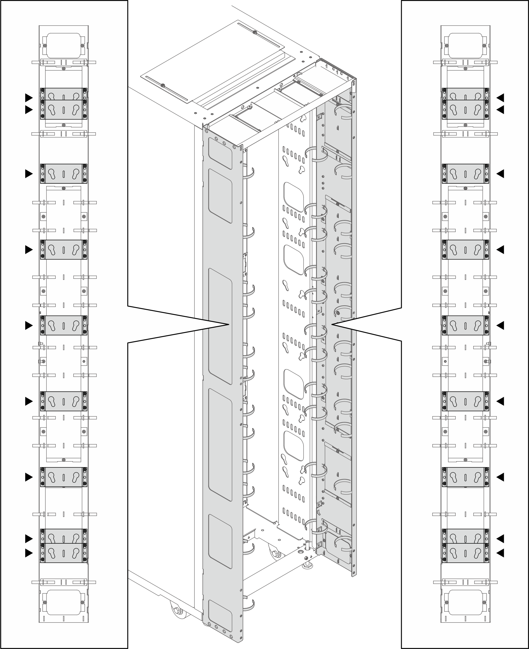
- Below illustration shows the locations for installing the brackets.Figure 13. Locations for installing the brackets with two keyhole slots
- If one or two brackets are installed in the locations indicated in the illustration below, the M6 hex head flange screw must be replaced with an M6 round head flange screw.Figure 14. Replacing the screw
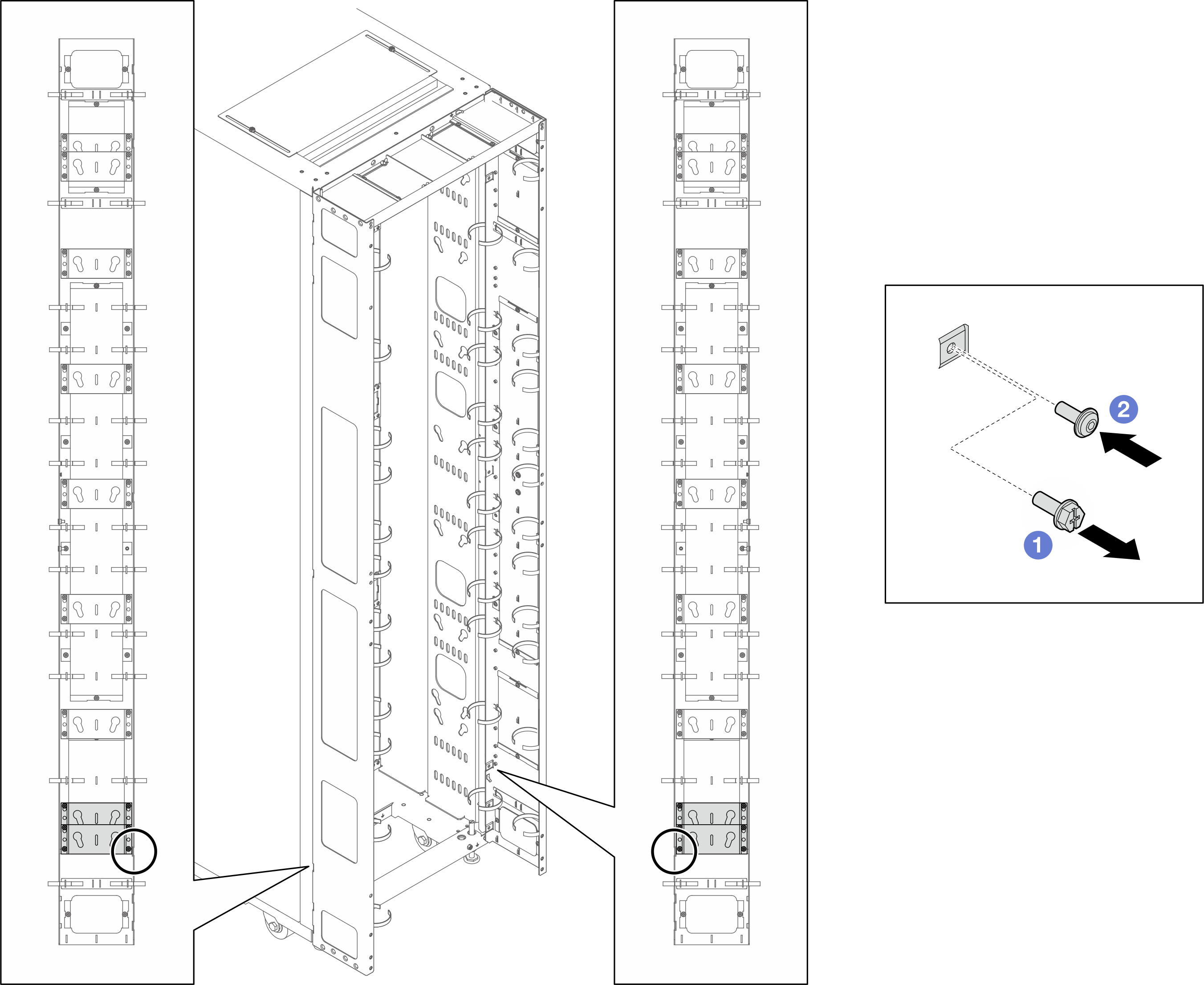
- Remove the M6 hex head flange screw.
- Install the M6 round head flange screw.
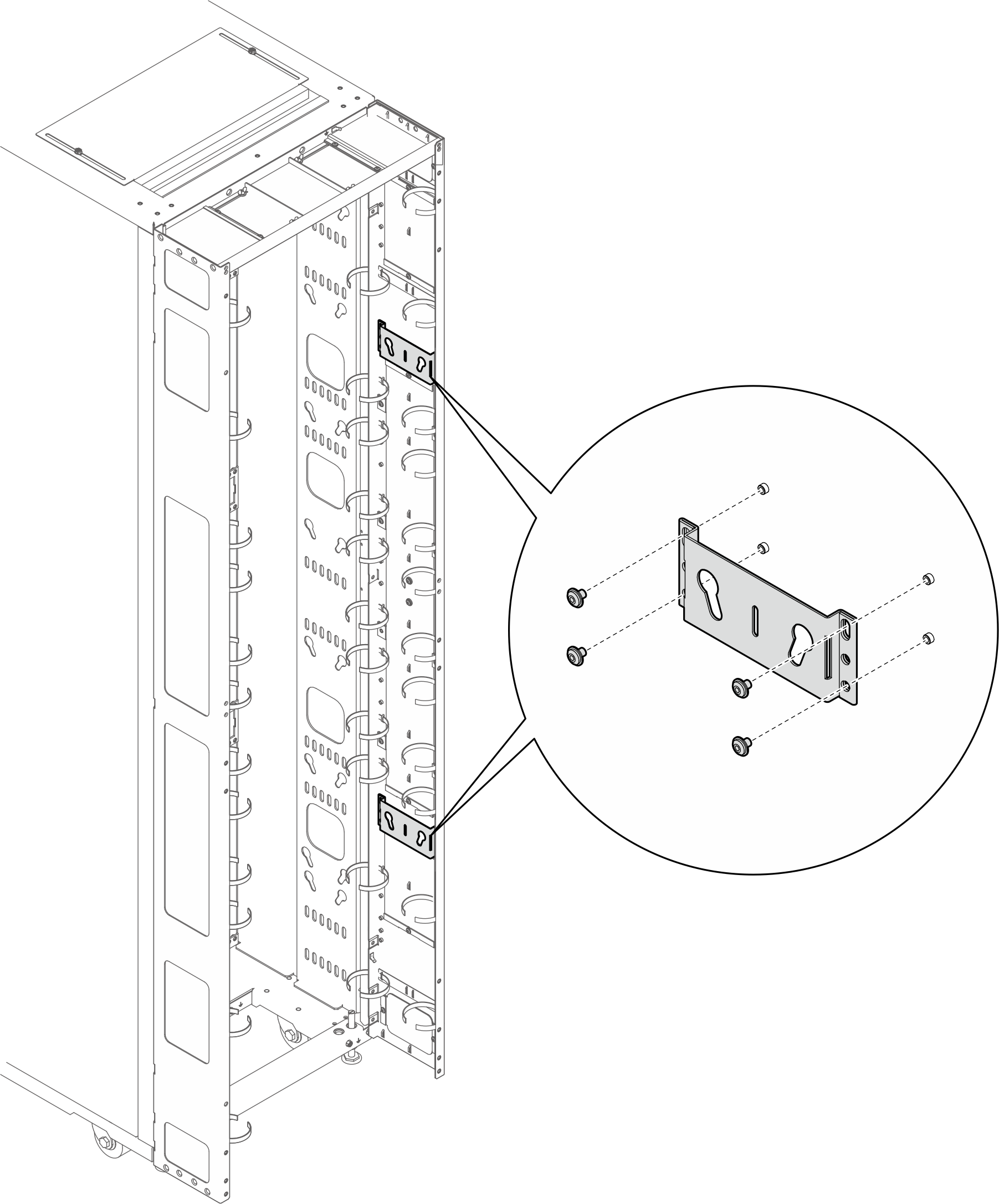
- Align the bracket with the extension panel, and secure it with four screws.Figure 15. Installing the bracket with two keyhole slots
- Insert the two PDU pegs into the keyhole slots on the brackets, and push down the PDU to secure it to the brackets. Choose the left or right slot for PDU installation based on the requirements.Figure 16. Installing the PDU
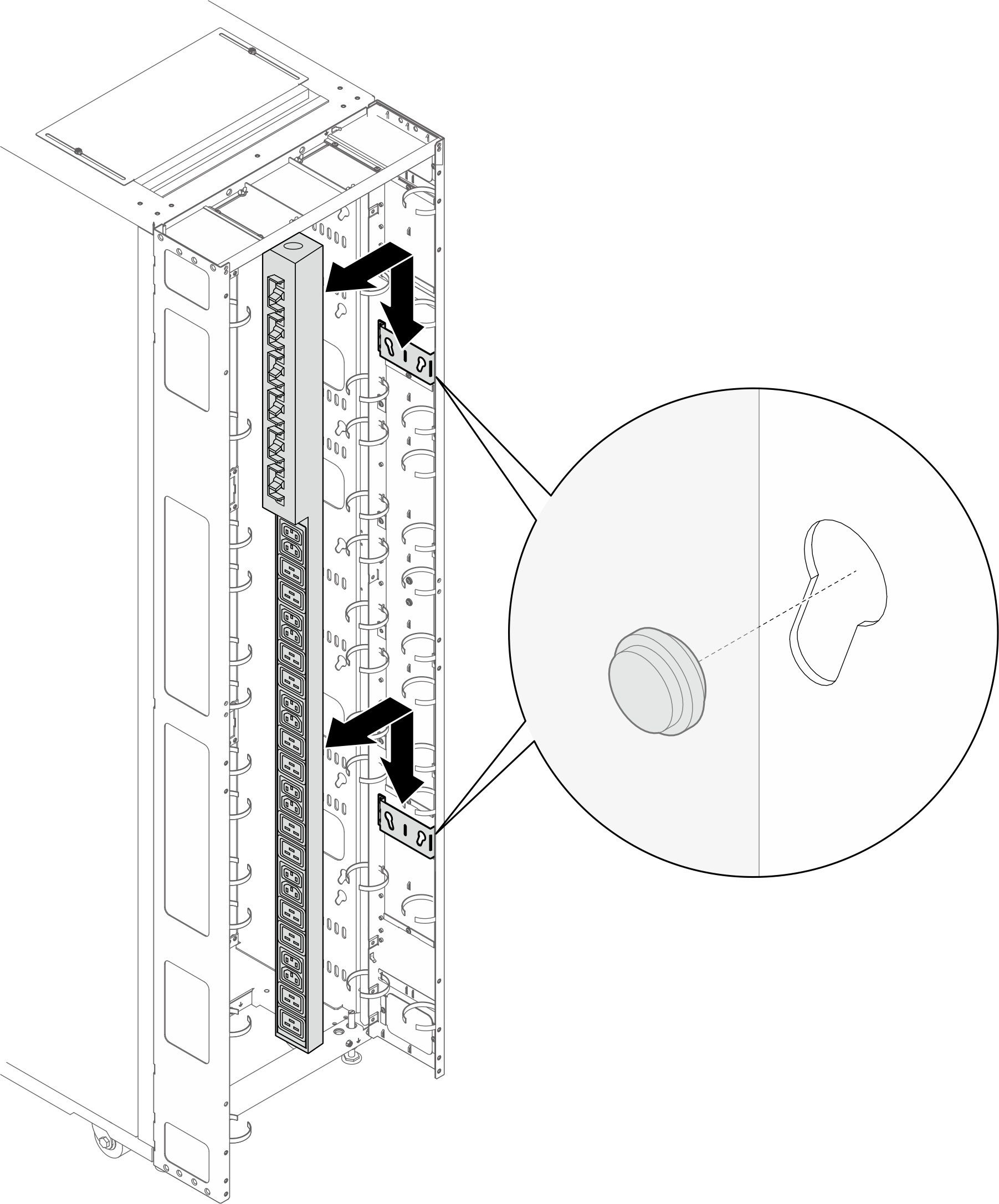 NotePDU can be rotated 180 degrees for installation with the input cable at the bottom.
- Below illustration shows the locations for installing the brackets.
- L-shaped bracket (up to two PDUs, or one PDU and one manifold)Note
- Below illustration shows the locations for installing the brackets.Figure 17. Locations for installing the L-shaped brackets
- If one or two brackets are installed in the locations indicated in the illustration below, the M6 hex head flange screw must be replaced with an M6 round head flange screw.Figure 18. Replacing the screw
- Remove the M6 hex head flange screw.
- Install the M6 round head flange screw.
- Align the bracket with the extension panel, and secure it with three screws. Choose the installation location for the bracket based on the orientation of the PDU.Figure 19. Installing the L-shaped bracket with the PDU facing the front of the rack cabinet
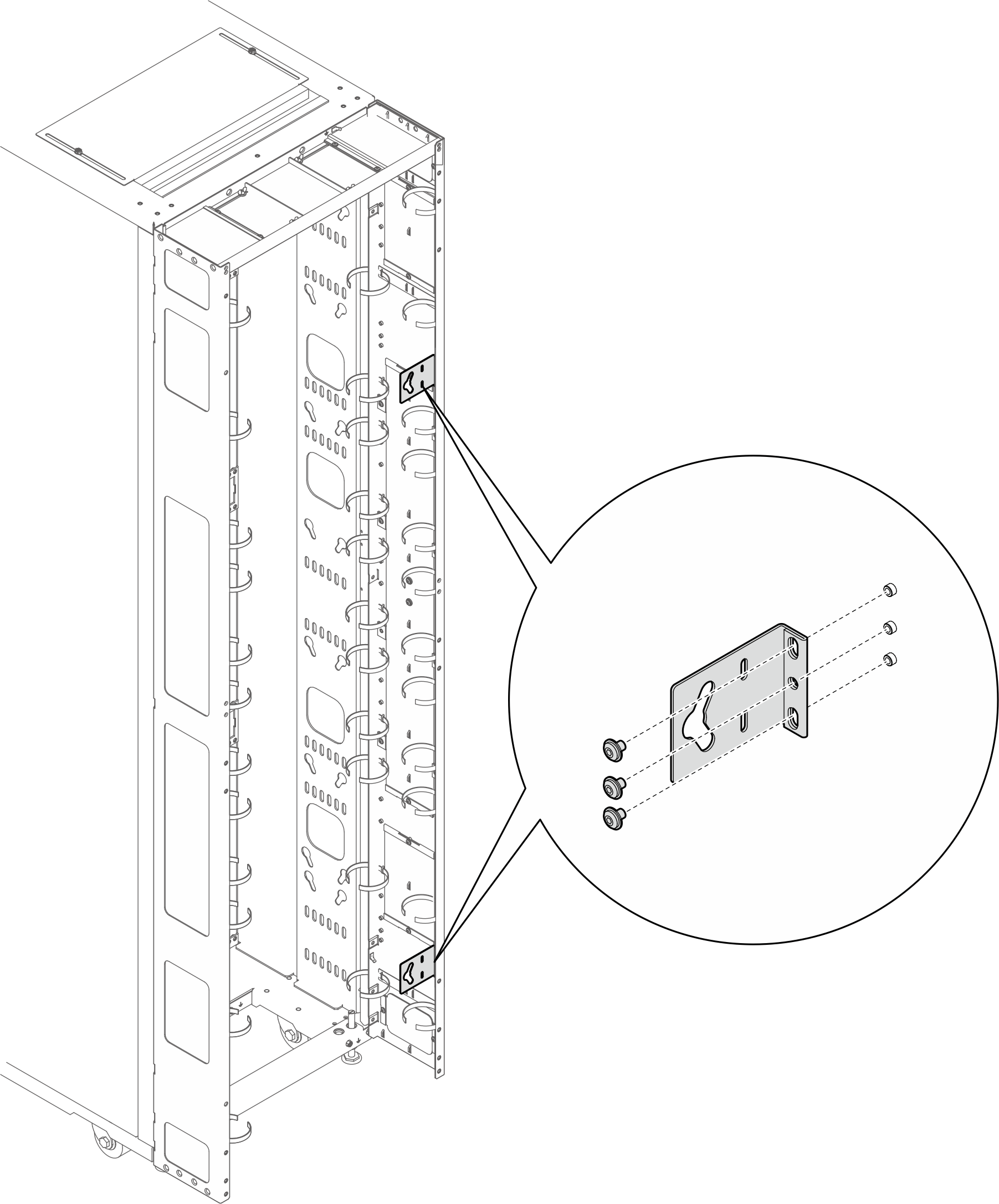 Figure 20. Installing the L-shaped bracket with the PDU facing the front of the rack cabinet
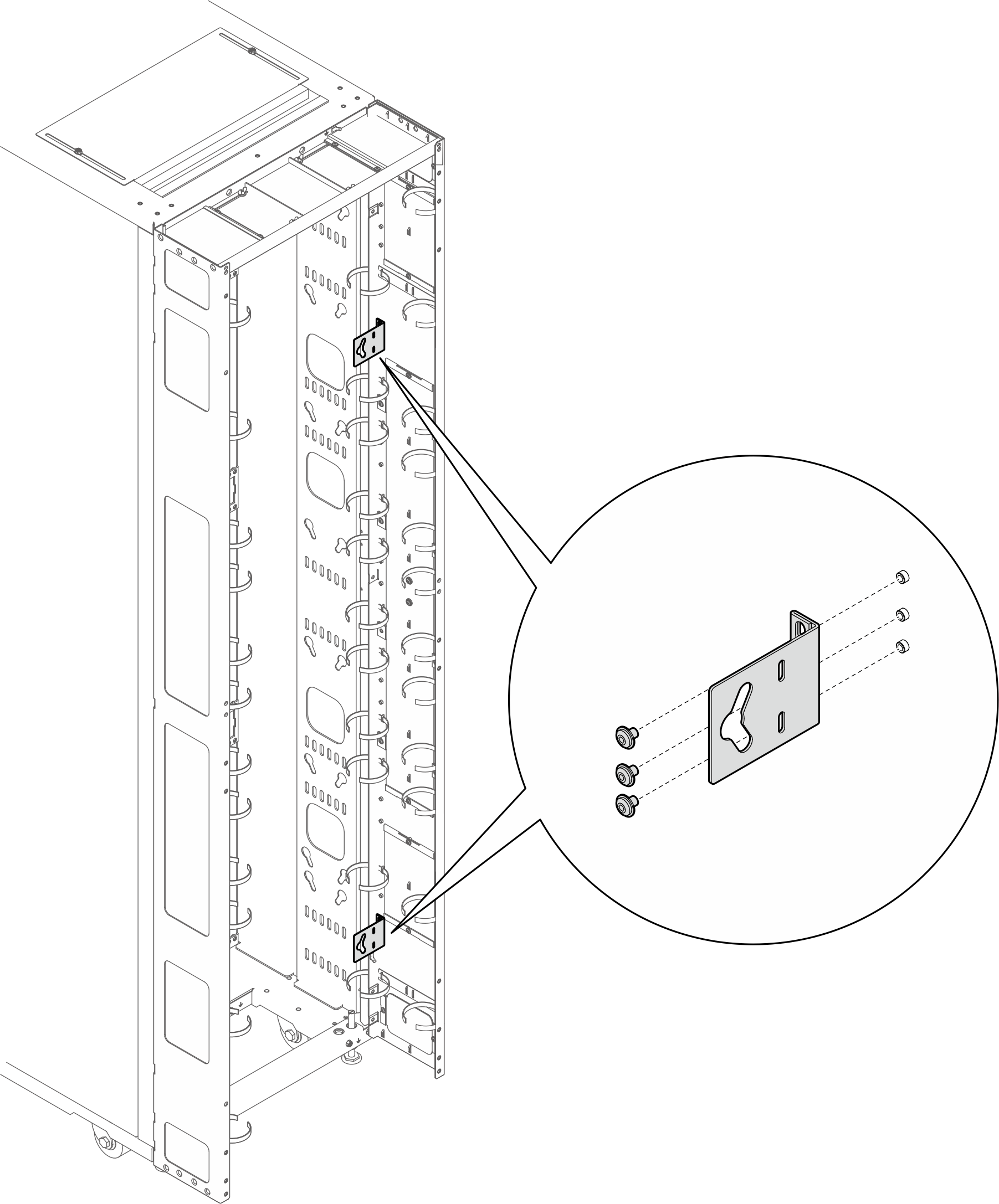
- Insert the two PDU pegs into the keyhole slots on the brackets, and push down the PDU to secure it to the brackets.Figure 21. Installing the PDU with the PDU facing the front of the rack cabinet
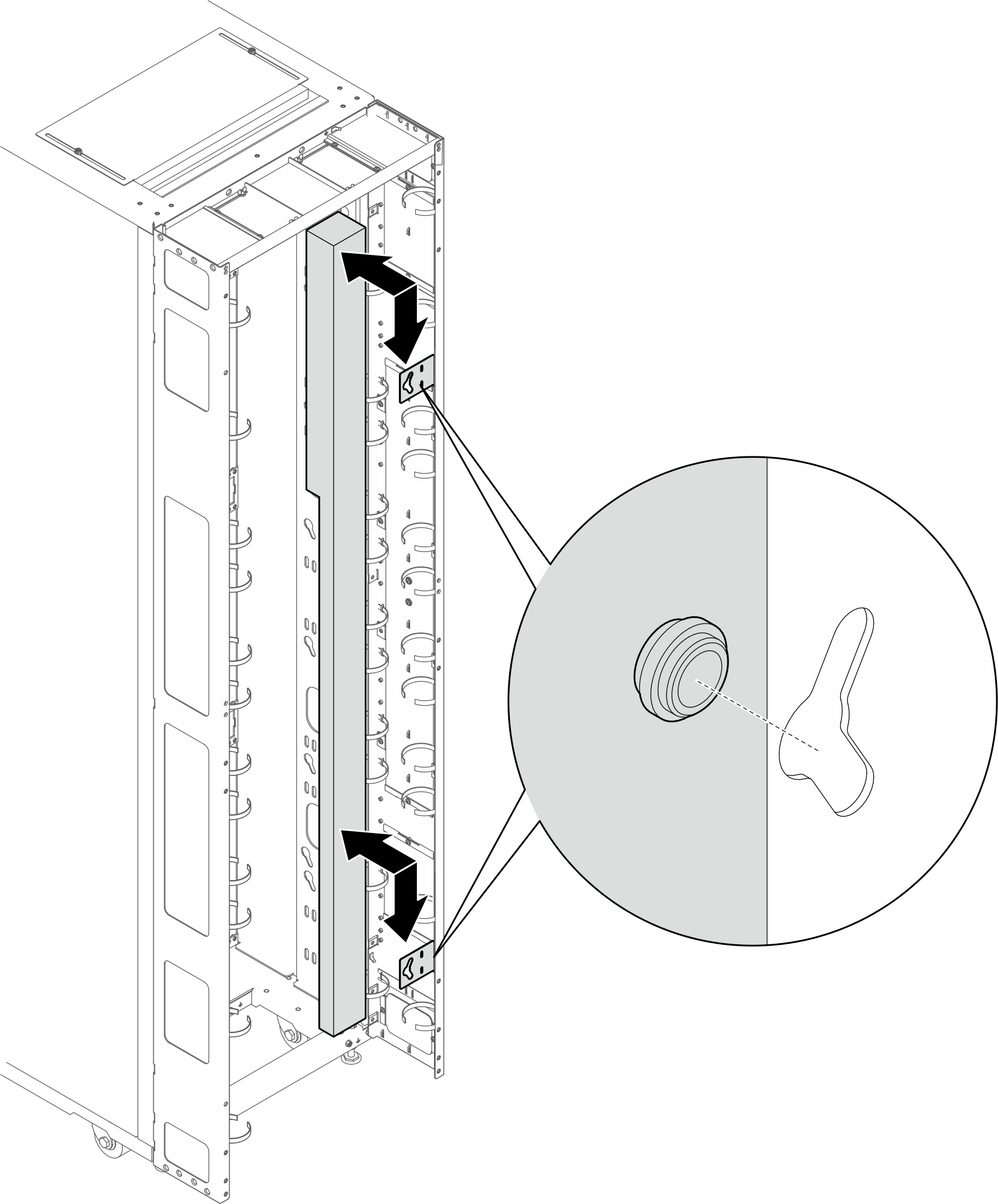 Figure 22. Installing the PDU with PDU facing the rear of the rack cabinet
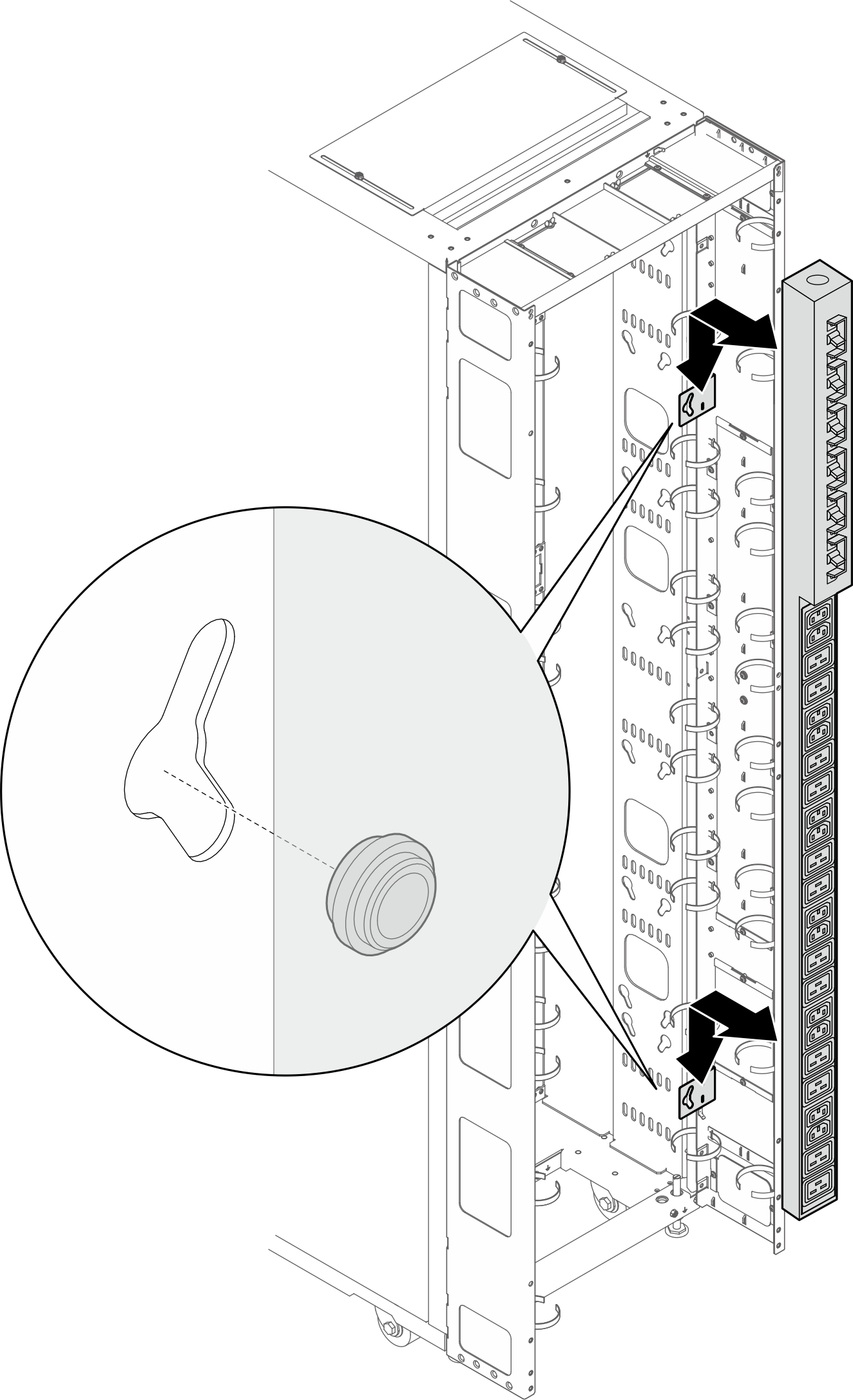
- Below illustration shows the locations for installing the brackets.
- Depending on the requirements, select one of the following methods to ensure there is sufficient space for routing cables.
Slide the brush panel
Figure 23. Sliding the brush panel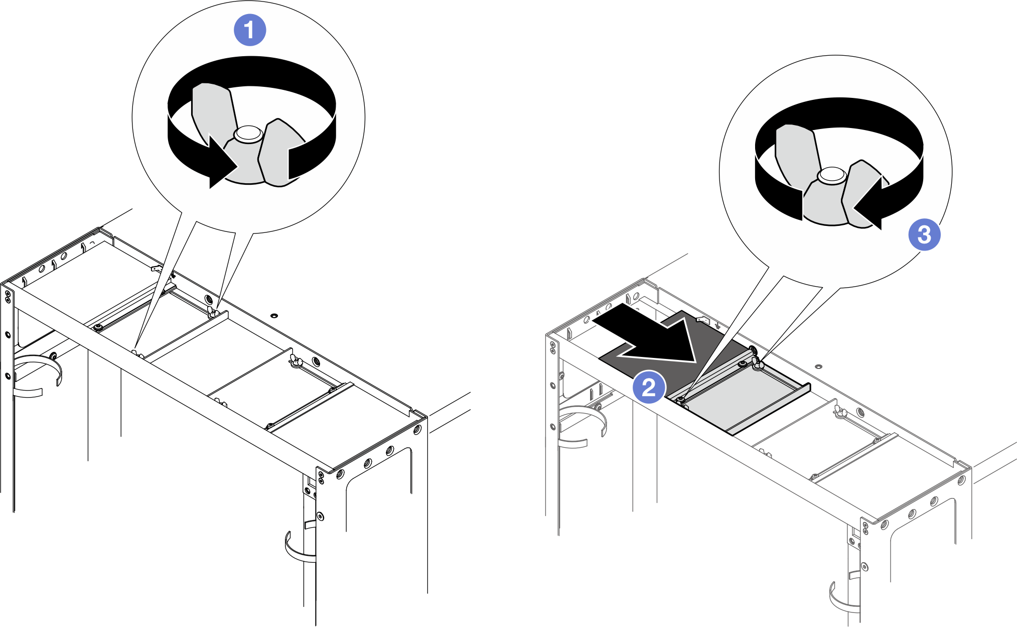
- Loosen the two screws that secure the baffle to the top cover.
- Slide the baffle and brush panel toward the center of the top cover.
- Tighten the two screws to secure the baffle.
Remove the brush panel
Figure 24. Removing the brush panel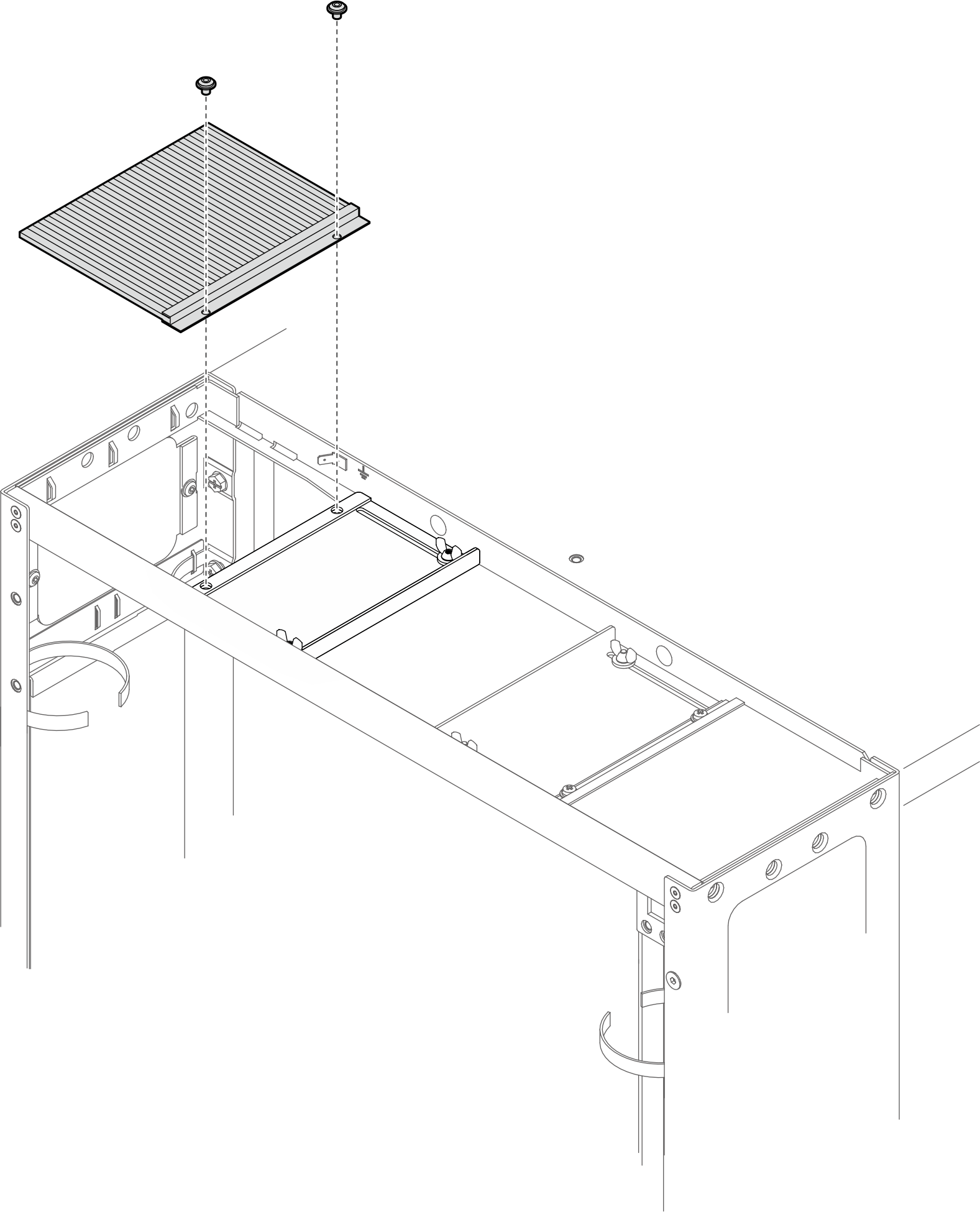
Loosen the two screws to remove the brush panel from the top cover.
Remove the brush panel and baffle
Figure 25. Removing the brush panel and baffle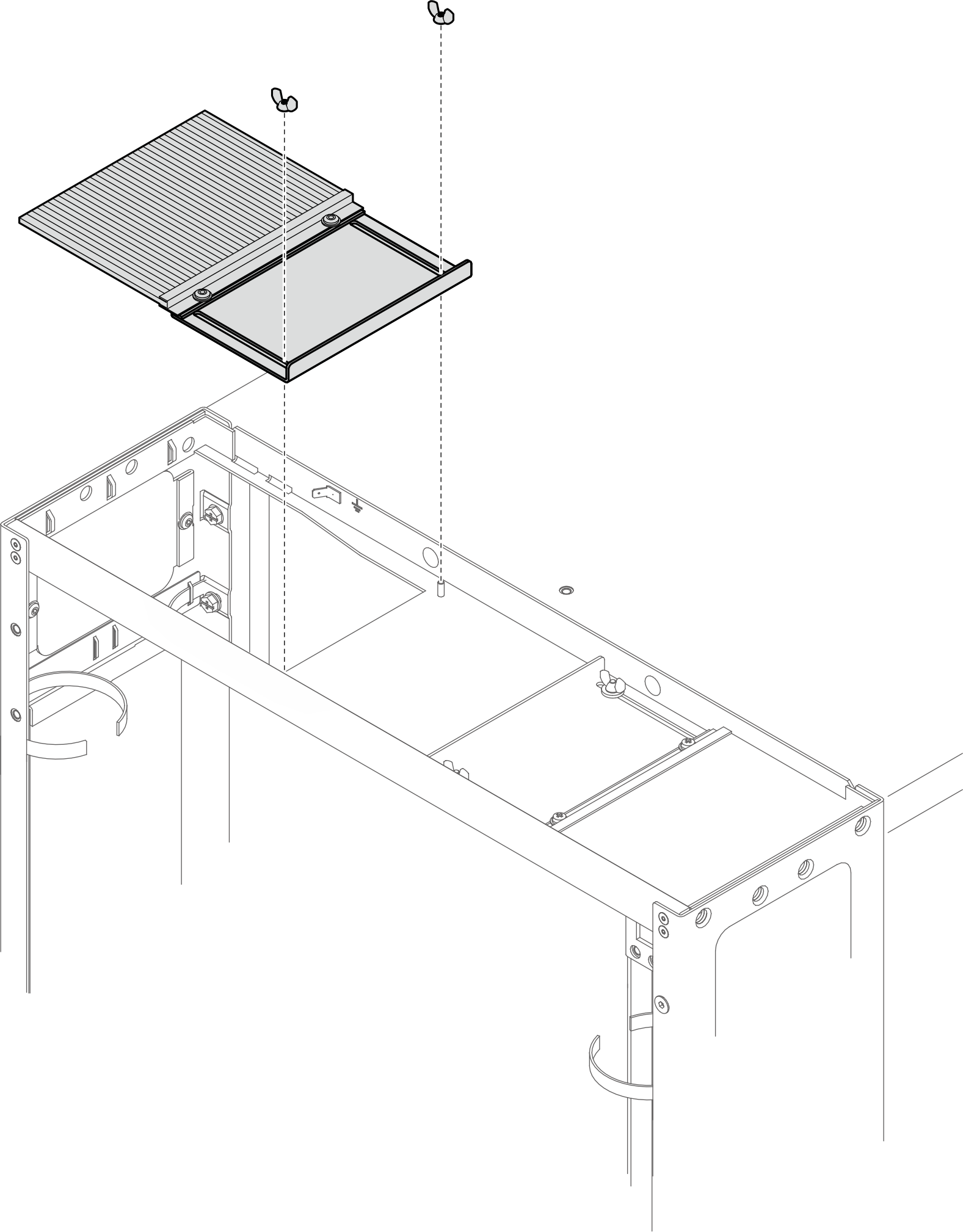
Loosen the two screws to remove the brush panel and baffle from the top cover.
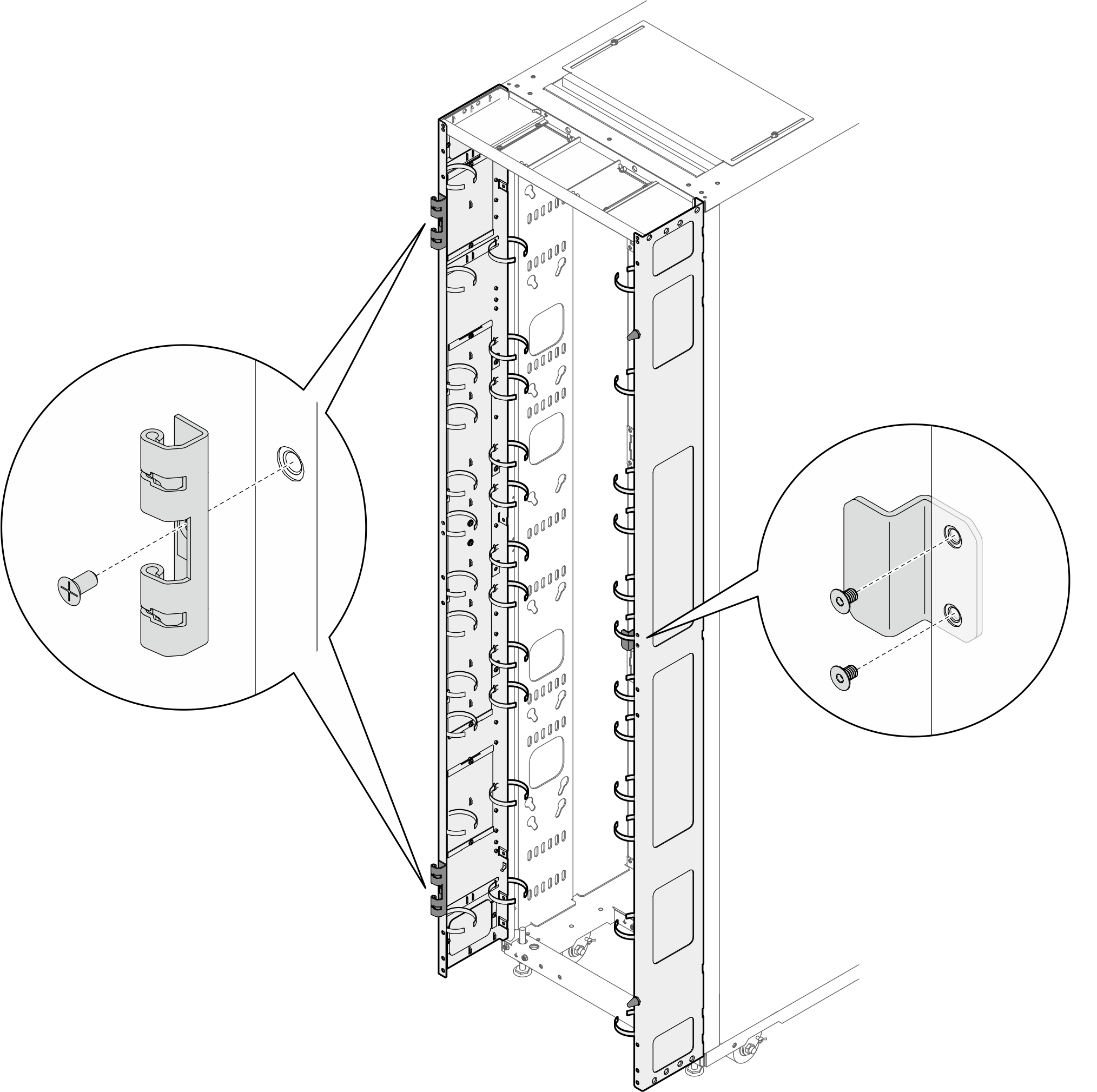
- Install the two door hinges and the door latch to the extension panels.Figure 26. Installing the door hinges and door latch
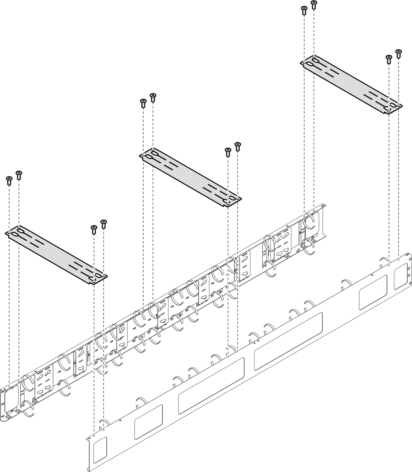
- If the rack needs to be shipped, install the three support brackets.NoteDepending on the requirement, remove the support brackets upon arrival at the site.Figure 27. Installing the support brackets
- Install the door back to the rack.Figure 28. Installing the door
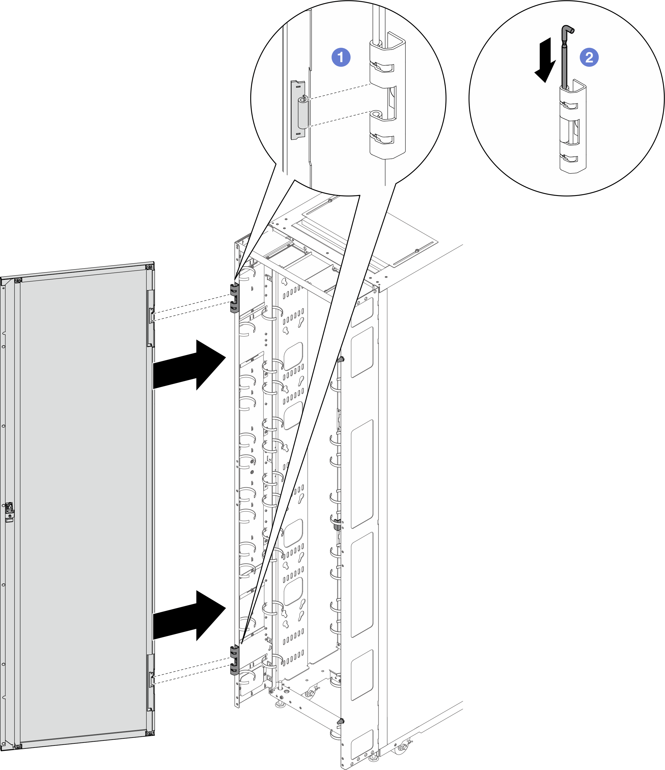
- Align the door with the hinges, and hold the door in place.
- Push the hinge pins down to the closed position so that the door is secured.