Install a 0/1U device into the rack
See this topic to learn how to install a 0/1U device into the rack side.
About this task
S001

DANGER
danger
Electrical current from power, telephone, and communication cables is hazardous.
To avoid a shock hazard:
- Connect all power cords to a properly wired and grounded electrical outlet/source.
- Connect any equipment that will be attached to this product to properly wired outlets/sources.
- When possible, use one hand only to connect or disconnect signal cables.
- Never turn on any equipment when there is evidence of fire, water, or structural damage.
- The device might have more than one power cord, to remove all electrical current from the device, ensure that all power cords are disconnected from the power source.
S013
DANGER
danger
Overloading a branch circuit is potentially a fire hazard and a shock hazard under certain conditions. To avoid these hazards, ensure that your system electrical requirements do not exceed branch circuit protection requirements. Refer to the information that is provided with your device for electrical specifications.
S014
CAUTION
Hazardous voltage, current, and energy levels might be present. Only a qualified service technician is authorized to remove the covers where the label is attached.
R009

CAUTION
Removing components from the upper positions in the Enterprise Rack cabinet improves rack stability during relocation. Follow these general guidelines whenever you relocate a populated rack cabinet within a room or building:
- Reduce the weight of the rack cabinet by removing equipment starting at the top of the rack cabinet. When possible, restore the rack cabinet to the configuration of the rack cabinet as you received it. If this configuration is not known, you must do the following:
- Remove all devices in the 32 U position and above.
- Make sure that the heaviest devices are installed in the bottom of the rack cabinet.
- Make sure that there are no empty U positions between devices installed in the rack cabinet below the 32 U position.
- If the rack cabinet that you are relocating is part of a suite of rack cabinets, detach the rack cabinet from the suite.
- Inspect the route that you plan to take, to eliminate potential hazards.
- Make sure that the route that you choose can support the weight of the loaded rack cabinet. See the documentation that comes with your rack cabinet for the weight of a loaded rack cabinet.
- Make sure that all door openings are at least 760 x 2030 mm (30 x 80 in.)
- Make sure that all devices, shelves, drawers, doors, and cables are secure.
- Make sure that the four leveling pads are raised to their highest positions.
- Make sure that no stabilizer bracket is installed on the rack cabinet.
- Do not use a ramp that is inclined more than 10 degrees.
- When the rack cabinet is in the new location, do the following:
- Lower the four leveling pads.
- Install stabilizer brackets on the rack cabinet.
- If you removed any devices from the rack cabinet, repopulate the rack cabinet from the lowest position to the highest position.
If a long-distance relocation is required, restore the rack cabinet to the configuration of the rack cabinet as you received it. Pack the rack cabinet in the original packaging material, or equivalent. Also, lower the leveling pads to raise the casters off the pallet and bolt the rack cabinet to the pallet.
This cabinet supports up to four units of 1U devices that are installed to the rack side.
Note
Each rack side space only allows two units of 1U or two units of 0U devices to be installed at the same time. Mixing 1U and 0U devices on the same rack side is not feasible.
Refer to corresponding instructions based on the installation scenario:
Install a 0U device
Procedure
Insert the two PDU pegs into the keyhole slots in the side of the rack cabinet, and push down the PDU to secure it to the rack.
Figure 1. Installing a 0U PDU
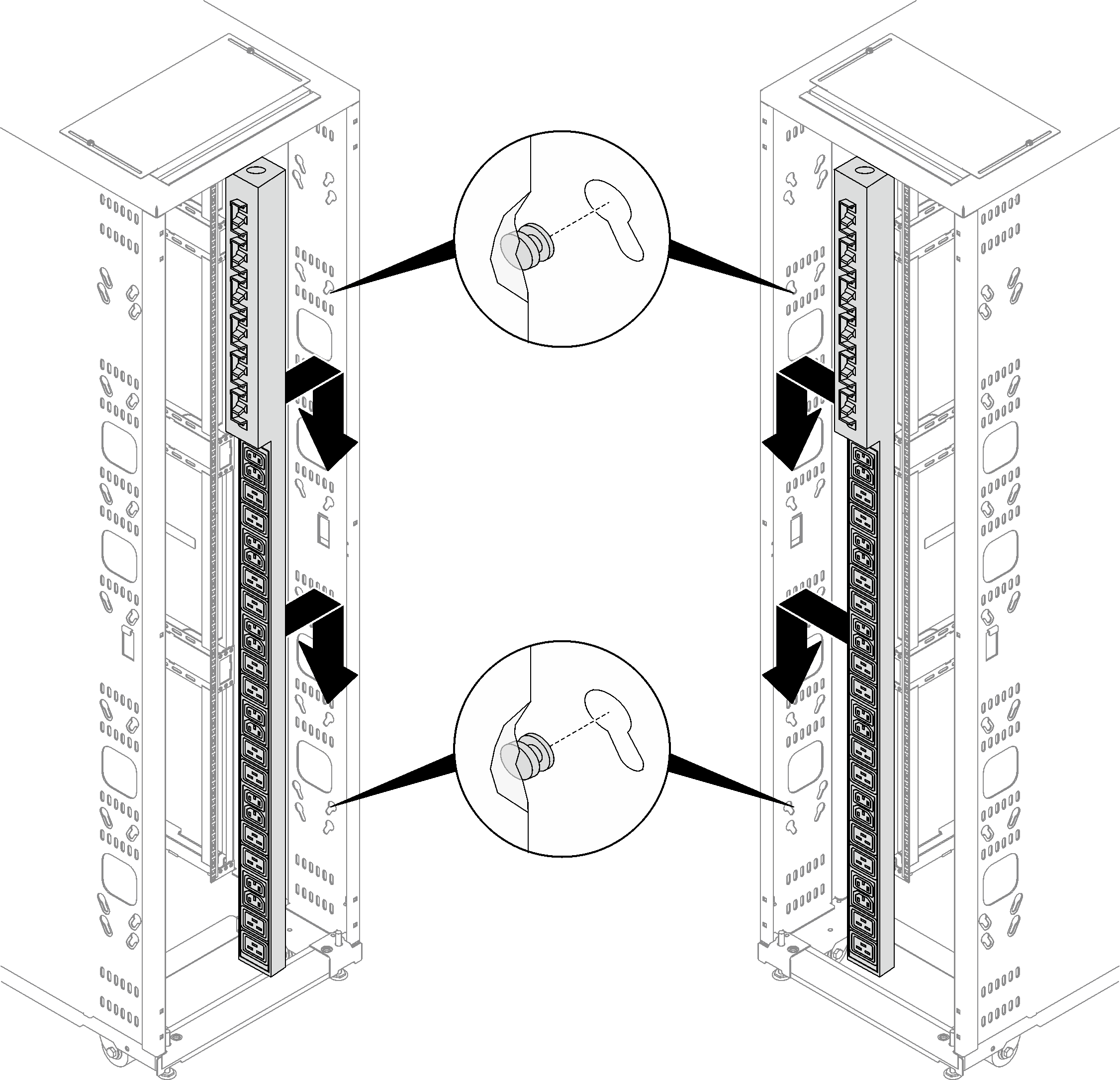
Note
0U PDU can be installed with sockets facing either rear or center of the rack cabinet.
Install a 1U PDU or console switch to the rack side
Procedure
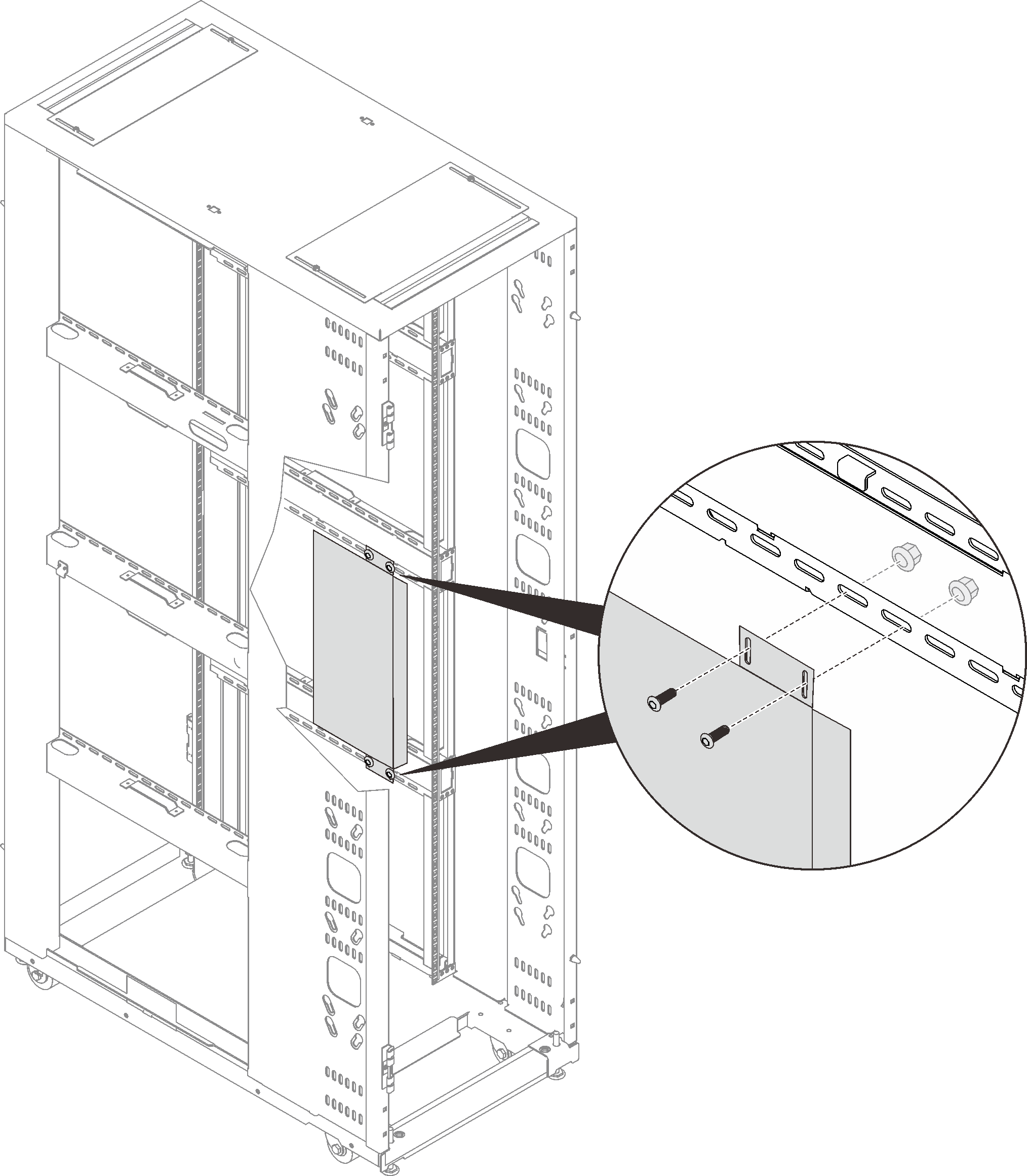
- Align the mounting brackets with the holes in the rack flange, and secure it with four sets of screw and nut.Figure 2. Installing a 1U device into the rack side
Install a 1U device into the side pocket
Procedure
- Install the device.Figure 3. Installing a 1U PDU or console switch
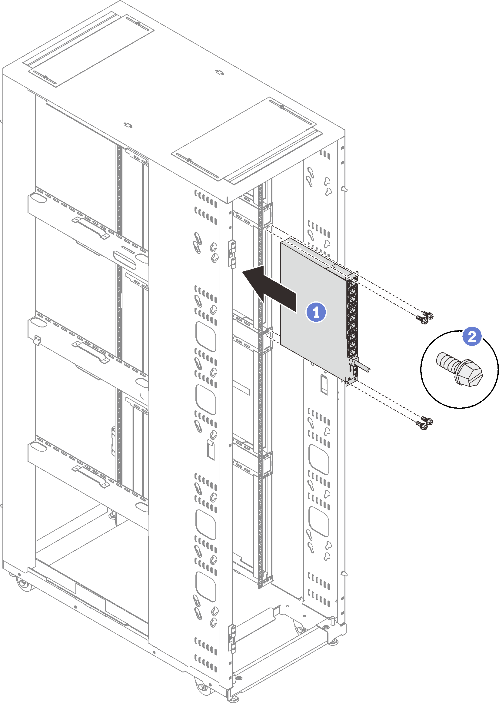
 Slide the device all the way into the side pocket.
 Secure the device with four M6 screws.
Give documentation feedback