ติดตั้ง 48U Advanced Rack Extension Kit พร้อมกับ RDHX
ดูหัวข้อนี้เพื่อเรียนรู้วิธีติดตั้ง 48U Advanced Rack Extension Kit และ RDHX
ชุดต่อขยายแร็คแต่ละหน่วยมาพร้อมกับความจุเพิ่มเติมสำหรับ 0U PDU สูงสุดสองตัวหรือ 0U PDU หนึ่งตัวและท่อร่วมหนึ่งตัวที่แต่ละด้านของแร็ค
ตู้แร็คแต่ละตู้รองรับชุดต่อขยายแร็คได้สูงสุดสองชุด (หนึ่งชุดที่ด้านหน้าและอีกหนึ่งชุดที่ด้านหลัง)
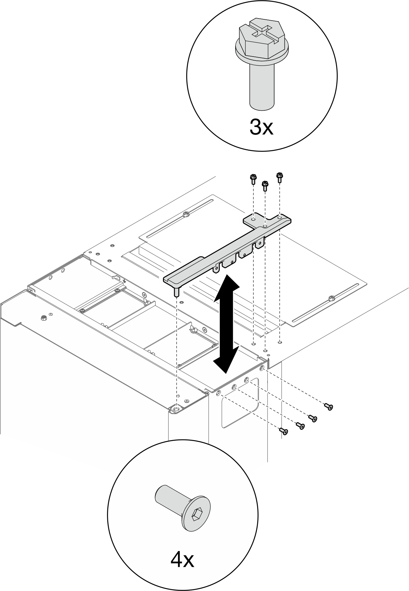
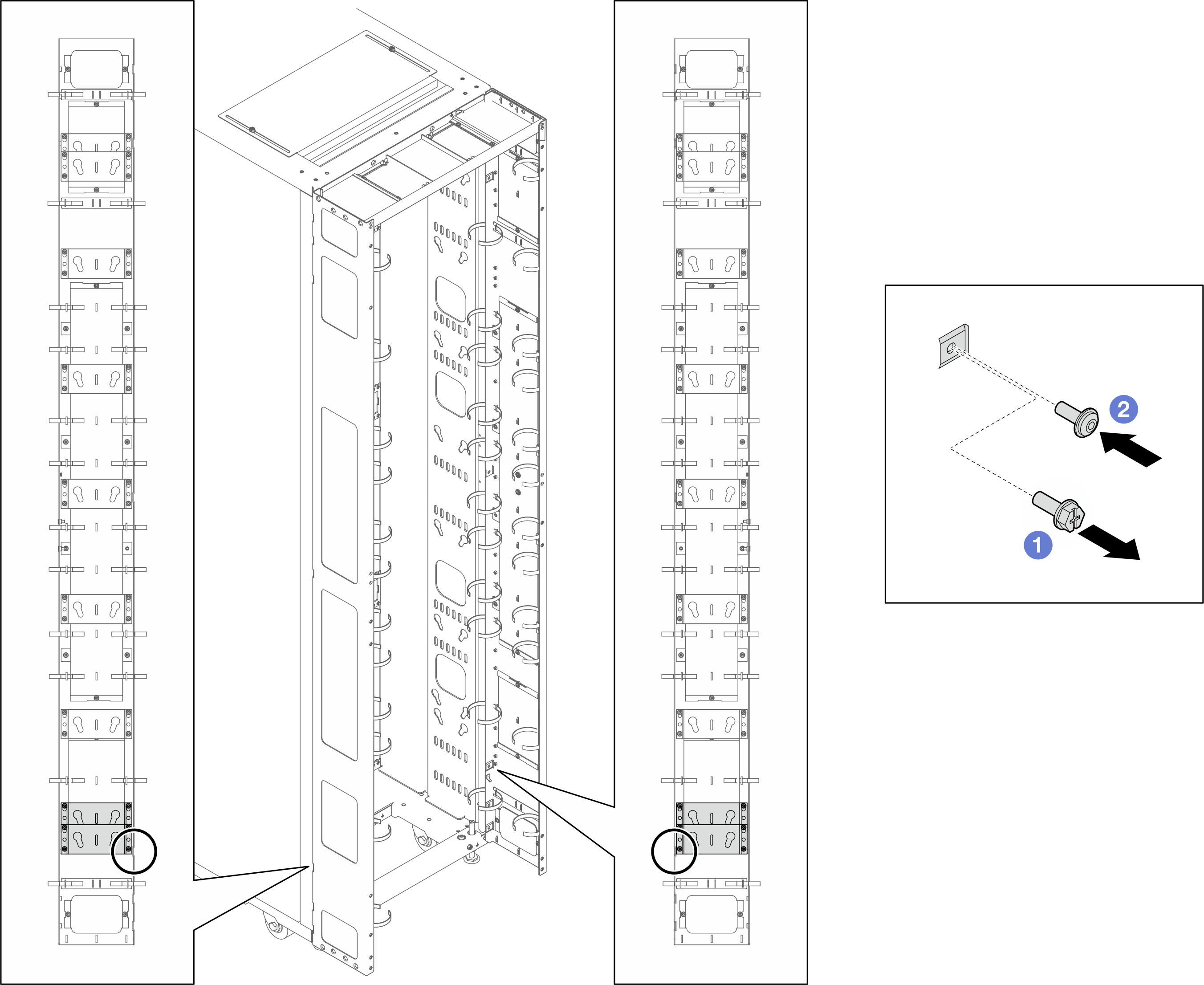
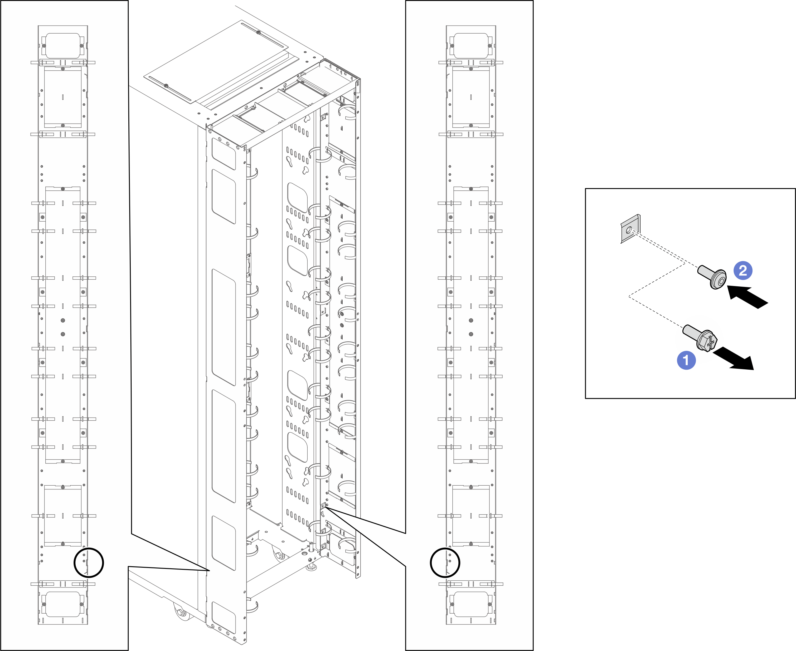
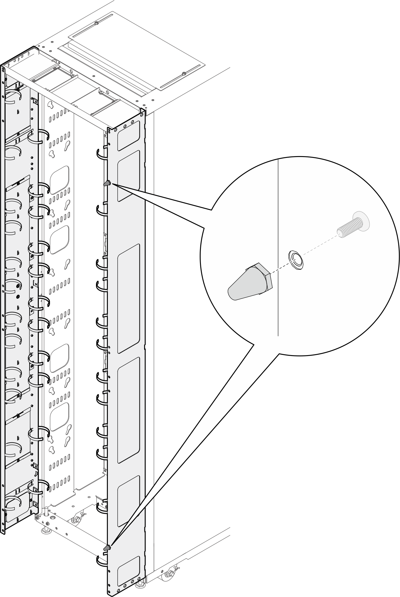
หากมีแผนที่จะติดตั้งชุดเชื่อมต่อในกรณีที่มีเพียงตู้แร็คข้างเคียงเพียงตู้เดียวที่ติดตั้งเพิ่มเติม ตรวจสอบให้แน่ใจว่าได้ติดตั้งชุดเชื่อมต่อก่อน (ดู ติดตั้งชุดเชื่อมต่อ) จากนั้น เพื่อเตรียมการสำหรับขั้นตอนนี้ ให้ถอดสกรูสองตัวออกจากส่วนบนและส่วนล่างของตู้ที่จะติดตั้งพร้อมกับชุดส่วนต่อขยาย แล้วข้ามไปที่ 2
รูปที่ 1. การถอดสกรูเพื่อเตรียมพร้อมสำหรับการติดตั้งส่วนต่อขยาย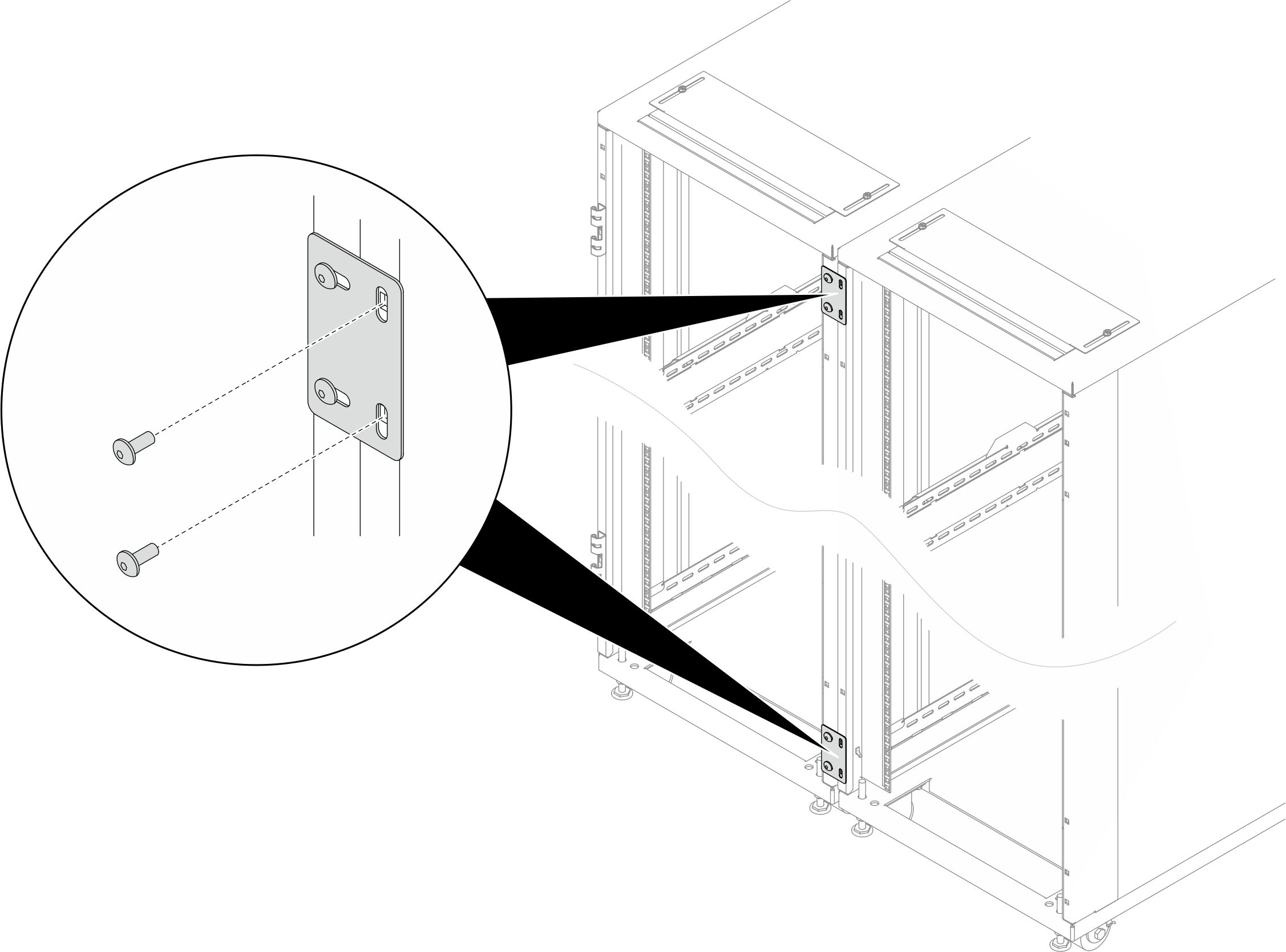
- เครื่องมือที่จำเป็น
- เครื่องมือหนึ่งชิ้นที่มีใบมีดพลาสติก/กรรไกรสำหรับเปิดบรรจุภัณฑ์
- ค้อนยางหนึ่งอันสำหรับปรับแนวแผงส่วนต่อขยายให้ตรงกับด้านข้างของแร็ค
- ไขควงหนึ่งอันพร้อมดอกไขควงหัวแฉกเบอร์ 3 สำหรับขันสกรู M6 ให้แน่น (9 ในหัวข้อย่อยถัดไป)
- ไขควงหัวบ๊อกซ์หนึ่งอันพร้อมดอกไขควงหกเหลี่ยมขนาด 10 มม. สำหรับขันสกรู M6 ให้แน่น (9 ในหัวข้อย่อยถัดไป)
- ลูกบล็อกหกเหลี่ยมขนาด 2.5 มม. หนึ่งตัวสำหรับขันสกรู M4 ให้แน่น (13 ในหัวข้อย่อยถัดไป)
- ลูกบล็อกหกเหลี่ยมขนาด 3 มม. หนึ่งตัวสำหรับขันสกรู M5 ให้แน่น (โครงยึด PDU/ท่อร่วม, ฝาครอบช่องบนแผงส่วนต่อขยาย)
- ลูกบล็อกหกเหลี่ยมขนาด 4 มม. หนึ่งตัวสำหรับขันสกรู M6 ให้แน่น (4 และ 14 ในหัวข้อย่อยถัดไป)
- ชุดต่อขยายมาพร้อมกับกระเป๋าเบ็ดเตล็ดซึ่งมีส่วนประกอบต่อไปนี้:รูปที่ 2. ชิ้นส่วน
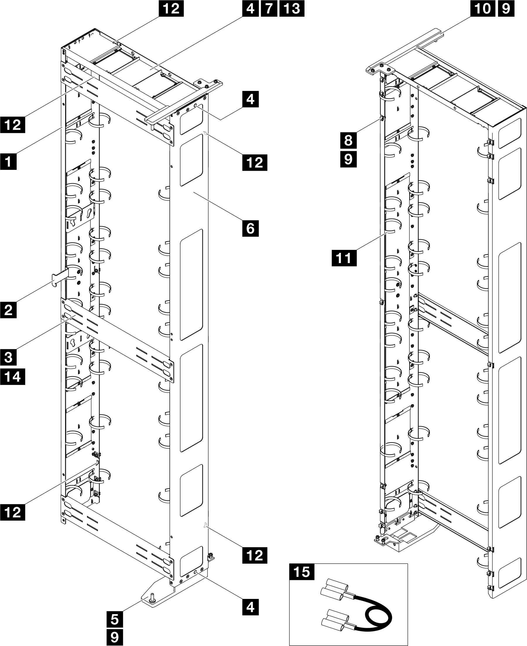
ไม่ รายละเอียด จำนวน ไม่ รายละเอียด จำนวน 1 แผงต่อขยายด้านซ้าย 1 9 สกรูหน้าแปลนหัวหกเหลี่ยม M6 x 16 มม. 21 2 แผ่นสลัก 1 10 บานพับด้านบนสำหรับ RDHX 1 3 โครงยึดรองรับ 3 11 โมดูลสายรัดเคเบิล 123 2 4 สกรูหัวจมแบน M6 x 16 มม. 10 12 แผ่นยึดต่อสายดิน 5 5 บานพับด้านล่างสำหรับ RDHX 1 13 สกรูหัวจมแบน M4 x 6 มม. 4 6 แผงต่อขยายด้านขวา 1 14 สกรูหัวจมแบน M6 x 12 มม. 12 7 ฝาครอบด้านบนส่วนต่อขยาย 1 15 สายดิน 4 3 8 น็อตตัวครอบ M6 14 - 1 สายรัดเคเบิลเป็นแบบถอดออกได้ ให้ถอดสายรัดออกจากแผงส่วนต่อขยายหากจำเป็น
- 2 สามารถเพิ่มความยาวให้สายรัดเคเบิลได้โดยนำสายรัดสองเส้นขึ้นไปมาเชื่อมต่อกัน
- 3 ใช้สายรัดเคเบิลเพื่อยึด PDU และท่อร่วมให้แน่นก่อนการจัดส่ง
- 4 ต่อปลายด้านหนึ่งของสายดินเข้ากับแผ่นยึดต่อสายดินบนแผงส่วนต่อขยาย แล้วต่อปลายอีกด้านเข้ากับแผ่นยึดต่อสายดินที่ใกล้ที่สุดบนแร็ค
รูปที่ 3. ประแจหกเหลี่ยมอัลเลน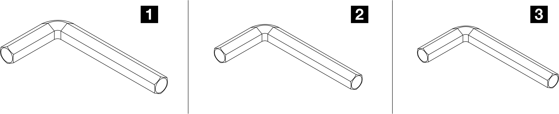
ไม่ รายละเอียด 1 ประแจหกเหลี่ยมอัลเลน 4 มม. 2 ประแจหกเหลี่ยมอัลเลน 3 มม. 3 ประแจหกเหลี่ยมอัลเลน 2.5 มม.
ขั้นตอน
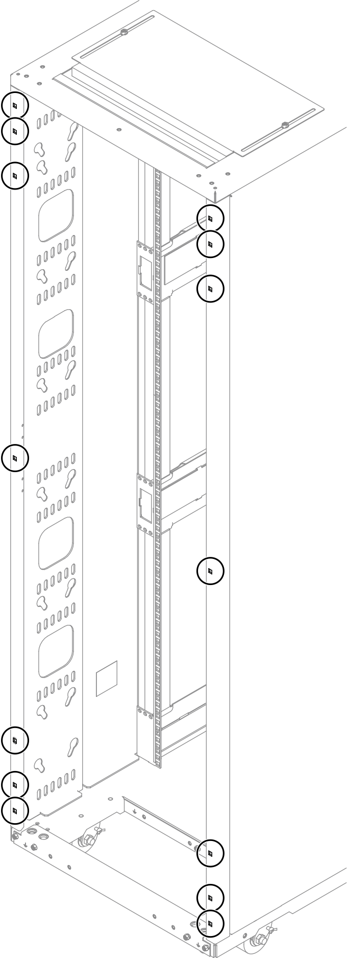
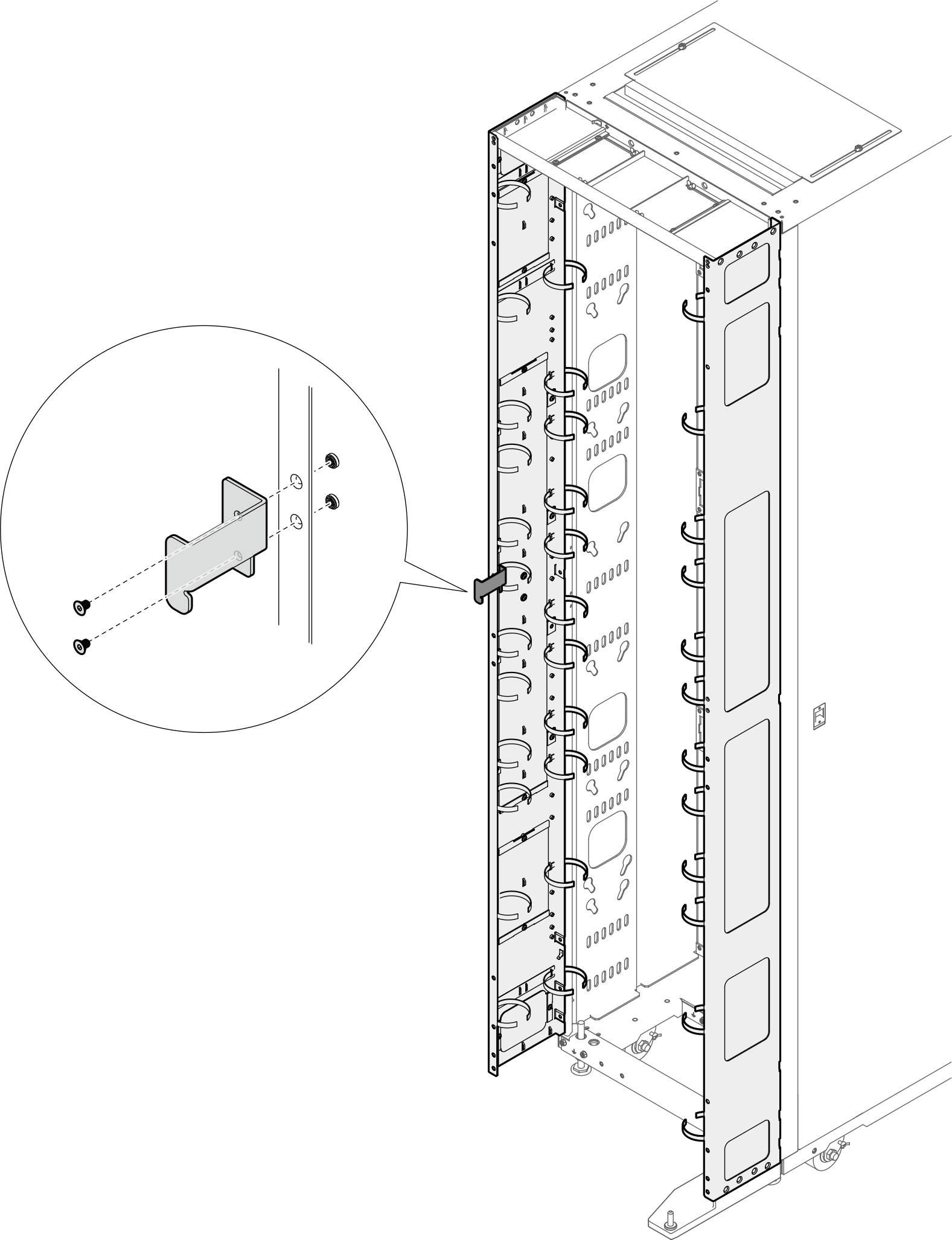
- ติดตั้งน็อตตัวครอบ M6 สิบสี่ตัวเข้ากับโครงแร็คด้วยเครื่องมือใส่น็อตตัวครอบหรือไขควงปากแบนรูปที่ 4. ตำแหน่งการติดตั้งน็อตตัวครอบ
 ด้วยเครื่องมือใส่น็อตตัวครอบรูปที่ 5. การติดตั้งน็อตตัวครอบด้วยเครื่องมือใส่น็อตตัวครอบ
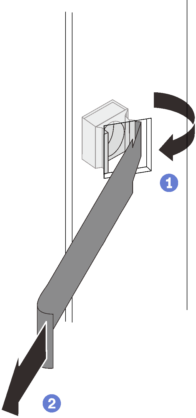
 สอดขอบด้านหนึ่งของน็อตตัวครอบเข้าไปในรูหน้าแปลนยึดเป้าหมาย และเกี่ยวขอบอีกด้านด้วยเครื่องมือสอดผ่านรูหน้าแปลน
 หมุนและดึงเครื่องมือเพื่อบังคับขอบน็อตอีกด้านเข้าไปในรูของหน้าแปลน และทำให้น็อตยึดให้แน่น
ด้วยไขควงปากแบนรูปที่ 6. การติดตั้งน็อตตัวครอบด้วยไขควงปากแบน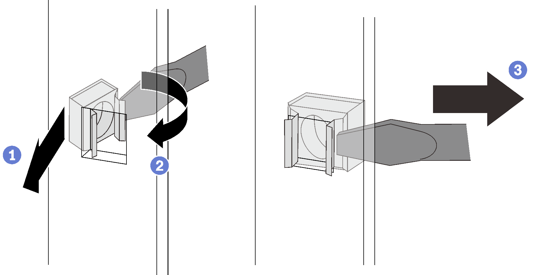
- สอดขอบด้านหนึ่งของน็อตตัวครอบเข้าไปในรูหน้าแปลนยึดเป้าหมาย
- กดและอัดขอบน็อตอีกด้านด้วยไขควงปากแบน และหมุนไขควงไปทางรูหน้าแปลนจนกระทั่งขอบน็อตเข้าไปในรู
 ปลดไขควงเพื่อยึดน็อตในรูหน้าแปลนติดตั้ง
- ติดตั้งบานพับด้านล่างรูปที่ 7. การยึดบานพับด้านล่าง
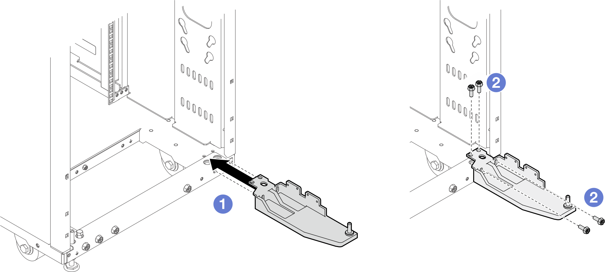 หมายเหตุอย่าขันสกรูสี่ตัวให้แน่นในขั้นตอนนี้
- จัดแนวบานพับให้ตรงกับแร็ค
- ยึดบานพับเข้ากับแร็คด้วยสกรูสี่ตัว
- ยึดแผงต่อขยายทั้งสองเข้ากับแร็คด้วยสกรูสิบสี่ตัวหมายเหตุ
อย่าขันสกรูสิบสี่ตัวให้แน่นในขั้นตอนนี้
หากเคยติดตั้งชุดเชื่อมต่อไว้ก่อนแล้ว ตรวจสอบให้แน่ใจว่าได้ถอดสกรูทั้งสองตัวที่ด้านบนและด้านล่างของตู้แร็คก่อน จากนั้น ขันสกรูผ่านแผงและชุดเชื่อมต่อ
รูปที่ 8. การติดตั้งแผงต่อขยาย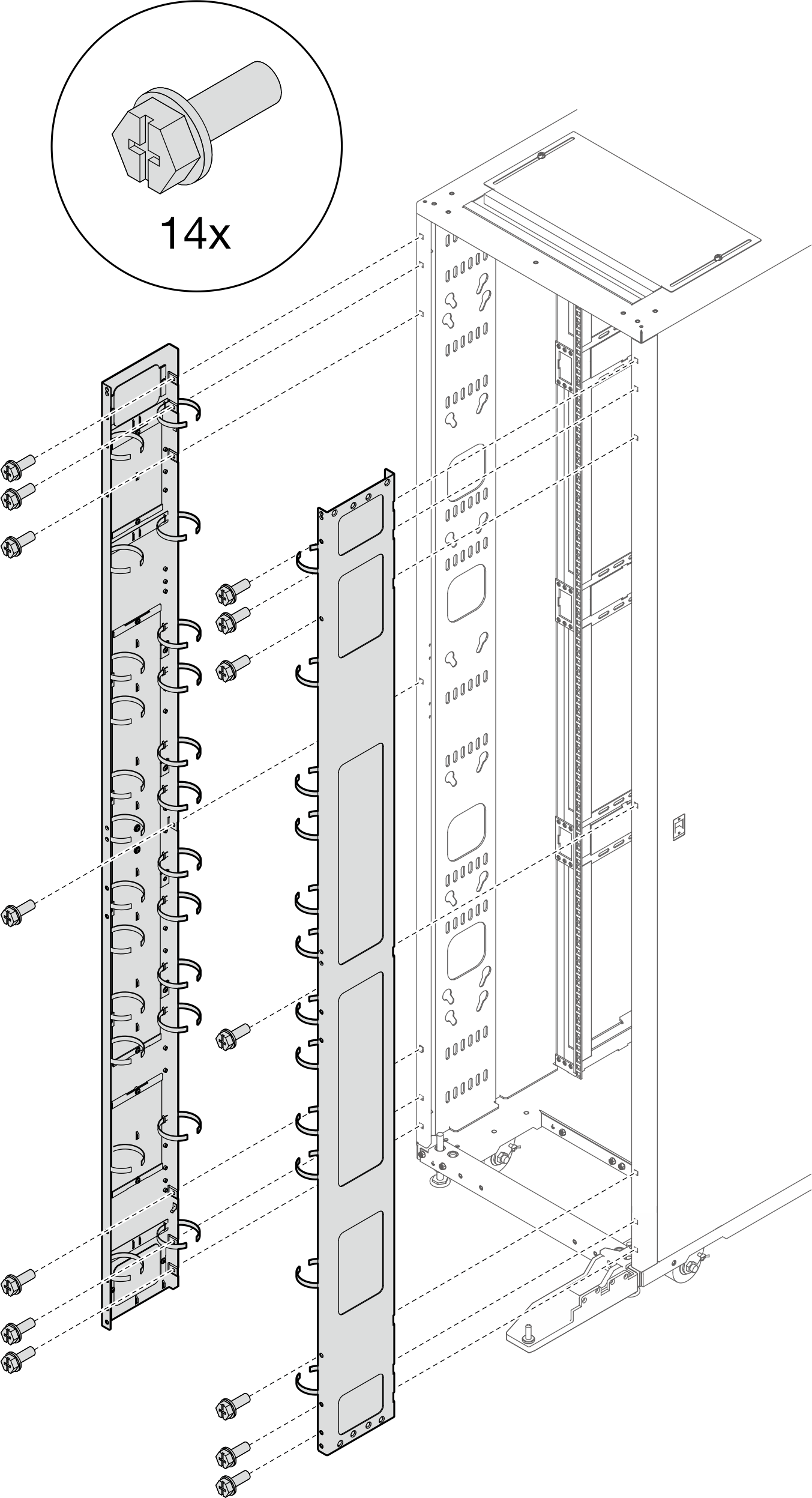
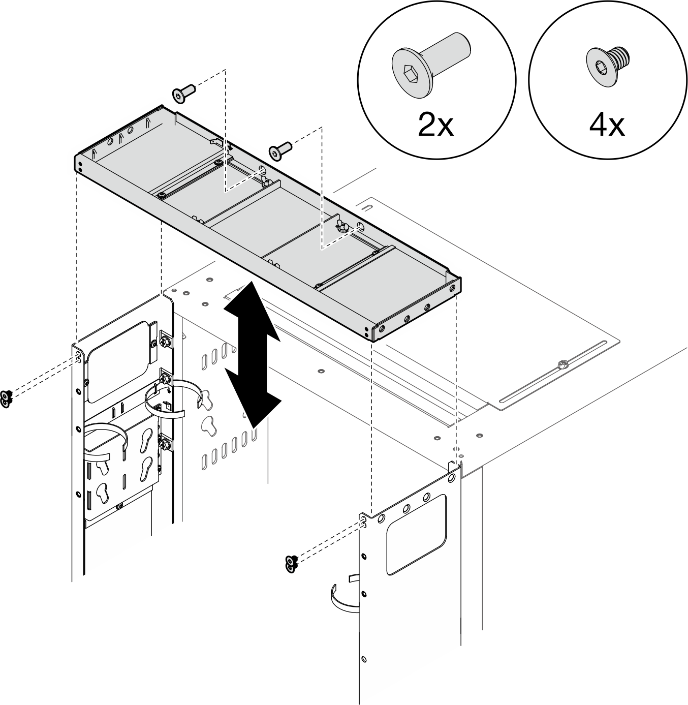
- จัดตำแหน่งฝาครอบด้านบนส่วนขยายให้ตรงกับรูสกรูบนแผงส่วนต่อขยาย และยึดให้แน่นด้วยสกรูหกตัวรูปที่ 9. การติดตั้งฝาครอบด้านบนส่วนต่อขยาย
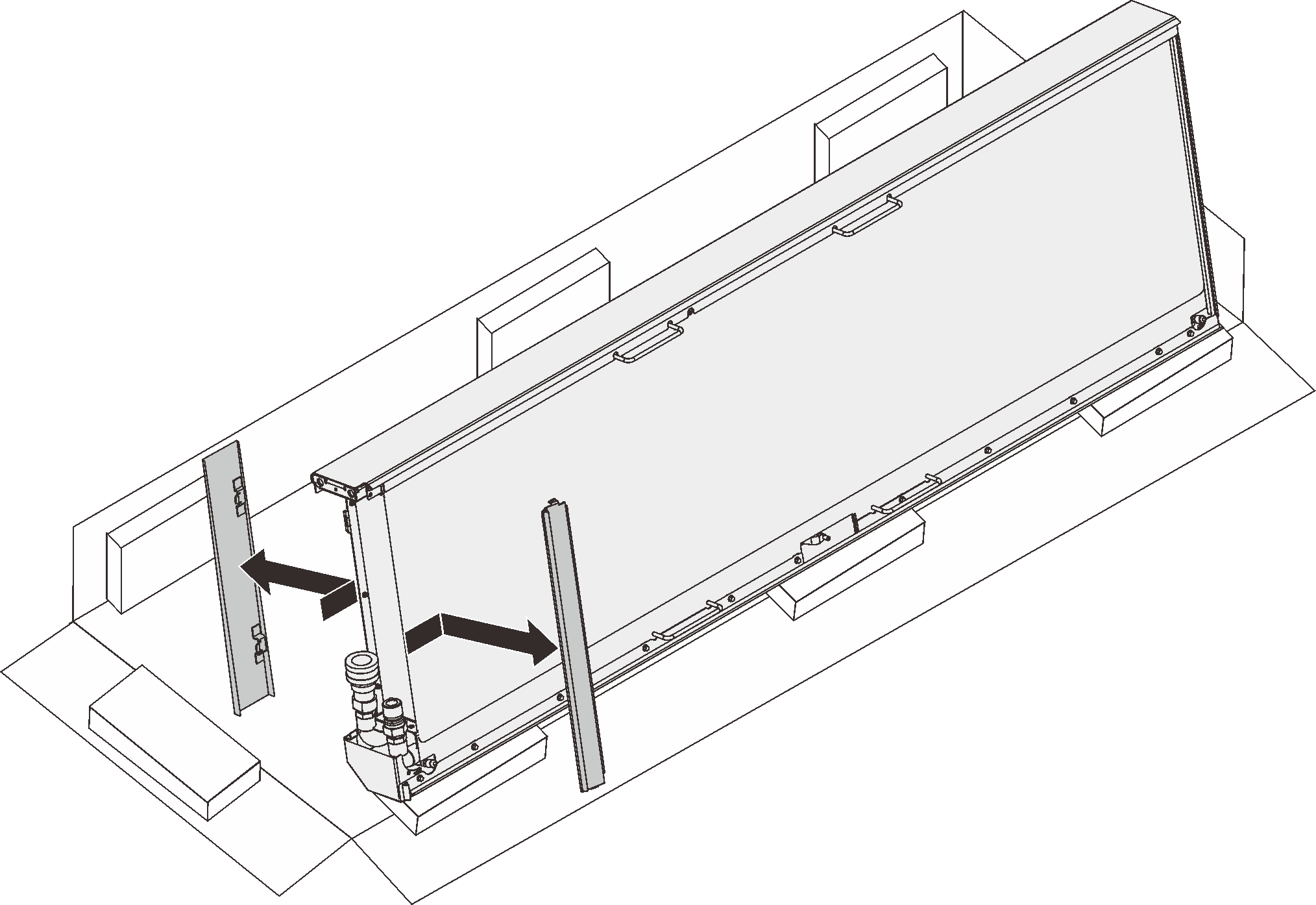
- ถอดฟิลเลอร์ออกจากแผงต่อขยายเพื่อเดินสาย โดยขึ้นอยู่กับข้อกำหนดรูปที่ 10. การถอดฟิลเลอร์
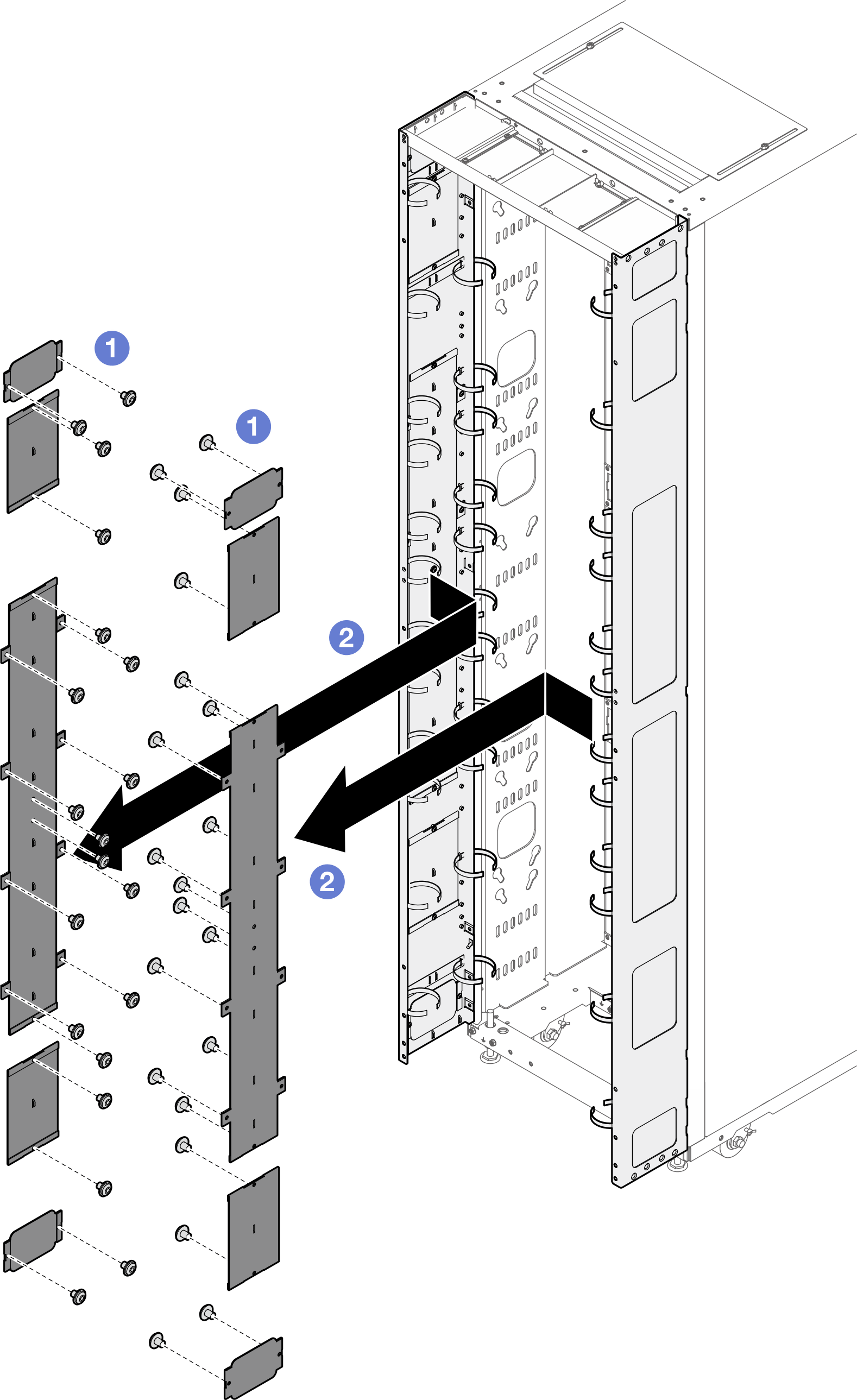
- คลายสกรูที่ยึดฟิลเลอร์เข้ากับแผงต่อขยาย
- ถอดฟิลเลอร์
- หากมีแผนที่จะติดตั้ง 0U PDU ไปยังแผงต่อขยาย ให้ทำตามขั้นตอนต่อไปนี้เลือกขั้นตอนการติดตั้งที่เกี่ยวข้อง โดยขึ้นอยู่กับข้อกำหนด
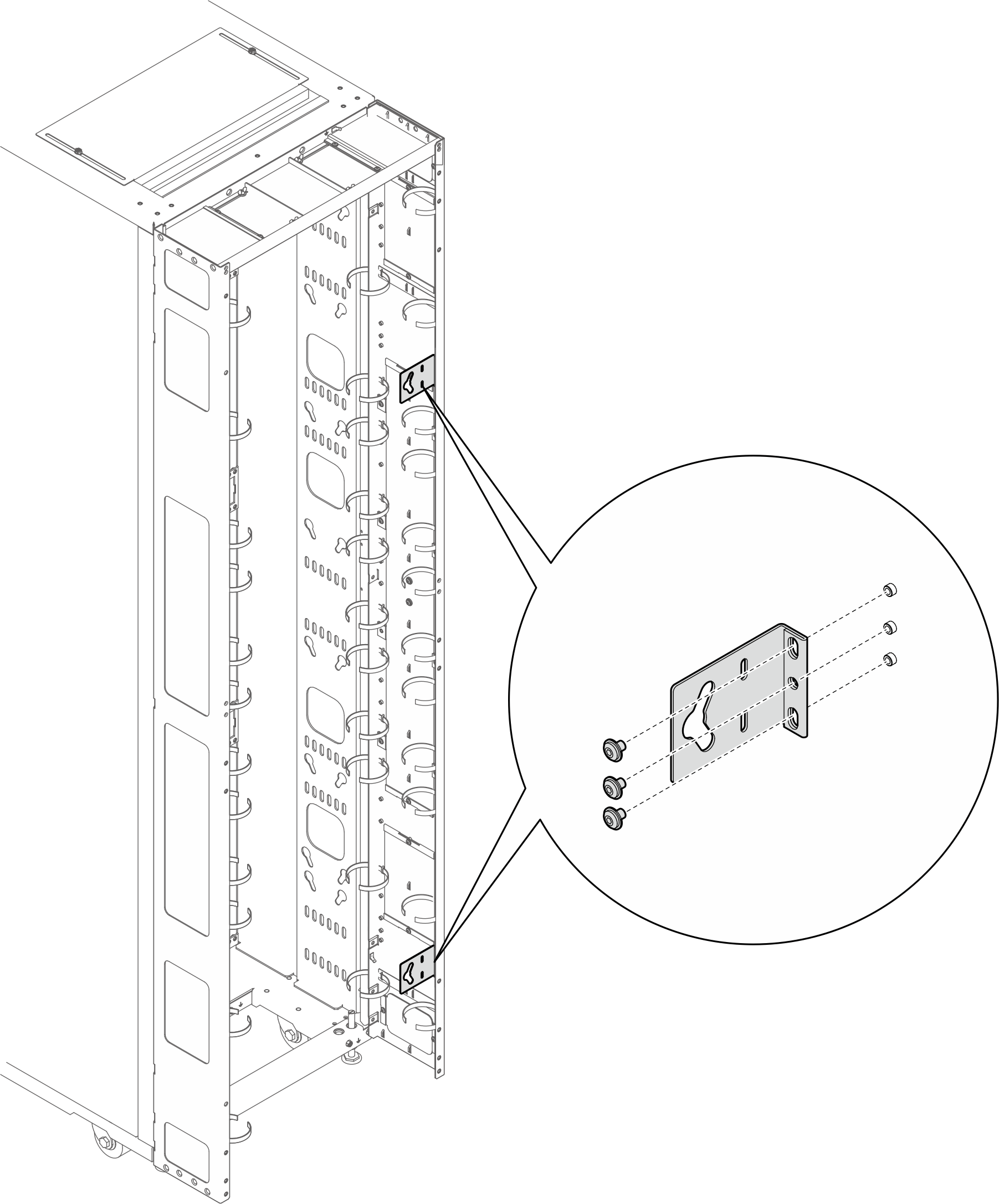
- โครงยึดที่มีช่องเสียบรูกุญแจสองช่อง (PDU สูงสุดสองตัว หรือ PDU หนึ่งตัวและท่อร่วมหนึ่งตัว)หมายเหตุ
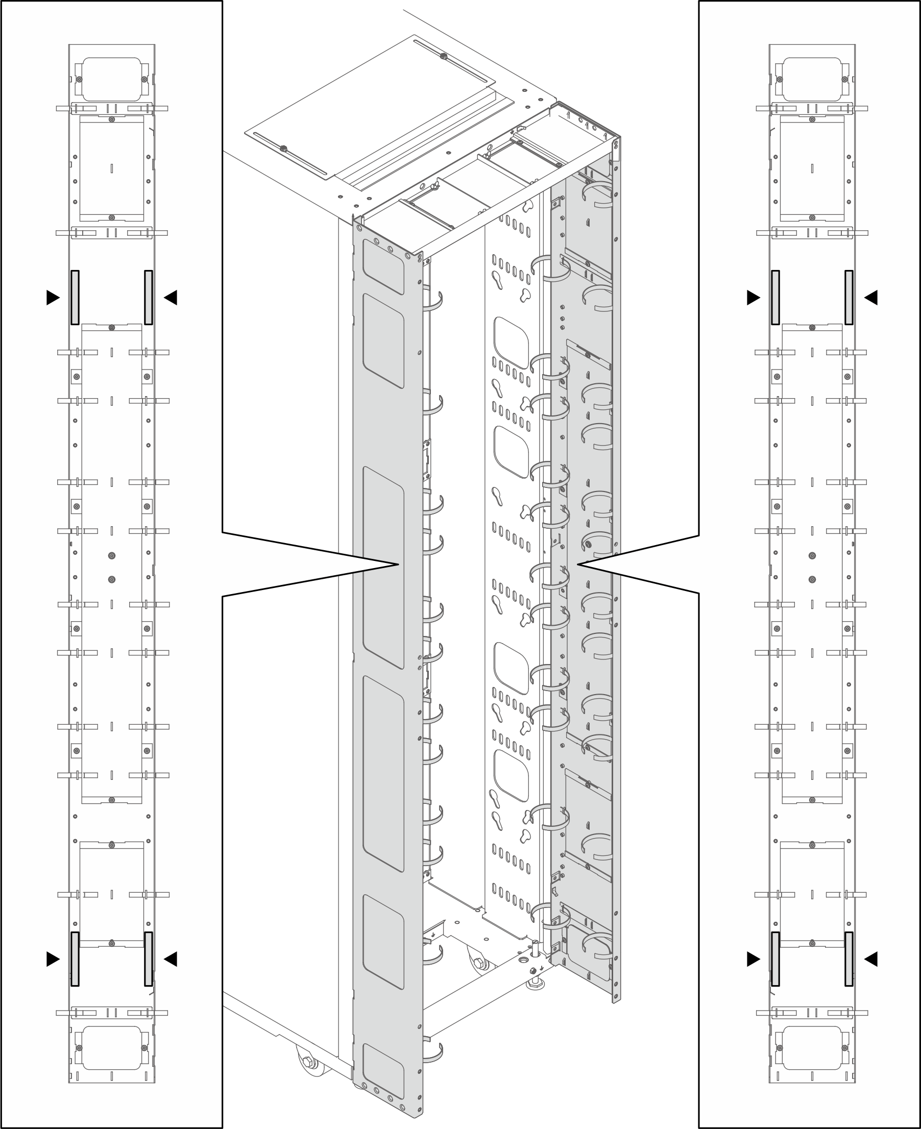
- ภาพประกอบด้านล่างแสดงตำแหน่งสำหรับติดตั้งโครงยึดรูปที่ 11. ตำแหน่งสำหรับติดตั้งโครงยึดที่มีช่องเสียบรูกุญแจสองช่อง
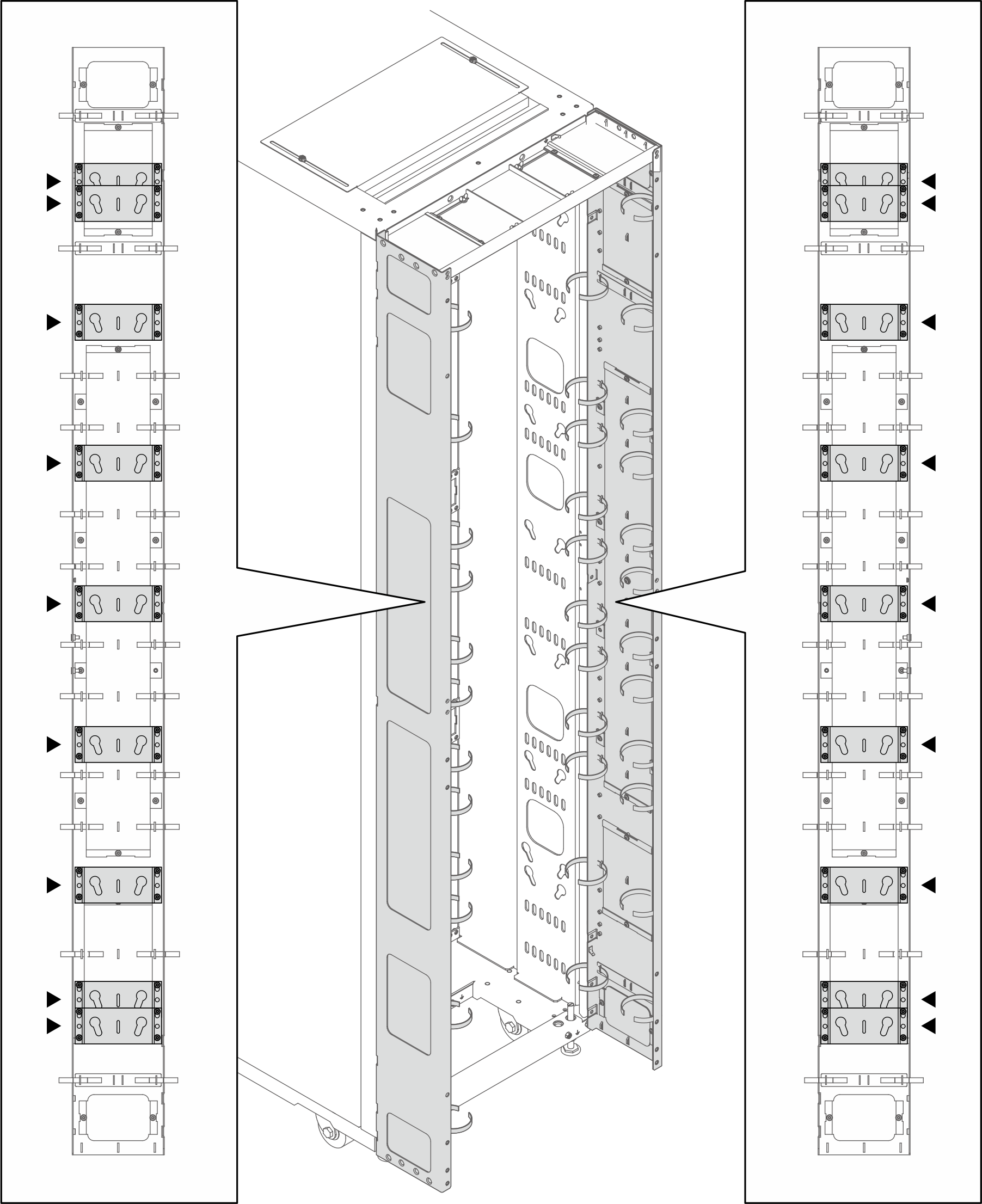
- หากมีการติดตั้งโครงยึดหนึ่งหรือสองตัวในตำแหน่งที่ระบุในภาพประกอบด้านล่าง จะต้องเปลี่ยนสกรูหน้าแปลนหัวหกเหลี่ยม M6 ด้วยสกรูหน้าแปลนหัวกลม M6รูปที่ 12. การเปลี่ยนสกรู
- ถอดสกรูหน้าแปลนหัวหกเหลี่ยม M6 ออก
- ติดตั้งสกรูหน้าแปลนหัวกลม M6
- จัดแนวโครงยึดให้ตรงกับแผงส่วนต่อขยาย และยึดให้แน่นด้วยสกรูสี่ตัวรูปที่ 13. การติดตั้งโครงยึดที่มีช่องเสียบรูสลักสองช่อง

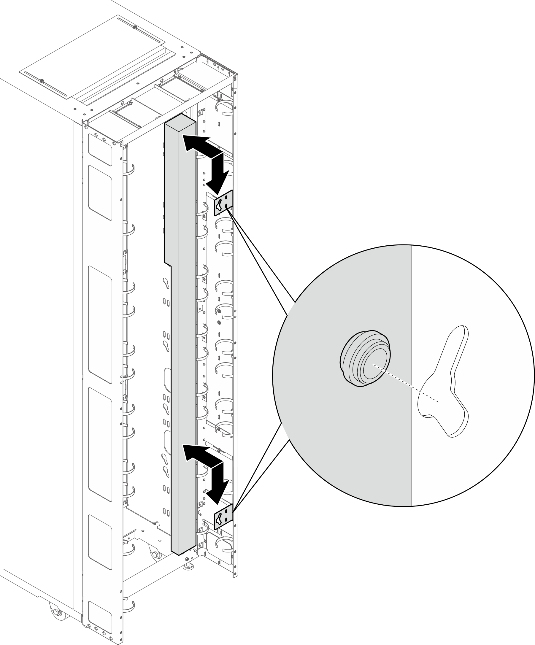
- ใส่หมุด PDU สองตัวลงในช่องรูกุญแจบนโครงยึด แล้วกด PDU ลงเพื่อยึดเข้ากับโครงยึด เลือกช่องซ้ายหรือขวาสำหรับการติดตั้ง PDU ตามความต้องการรูปที่ 14. การติดตั้ง PDU
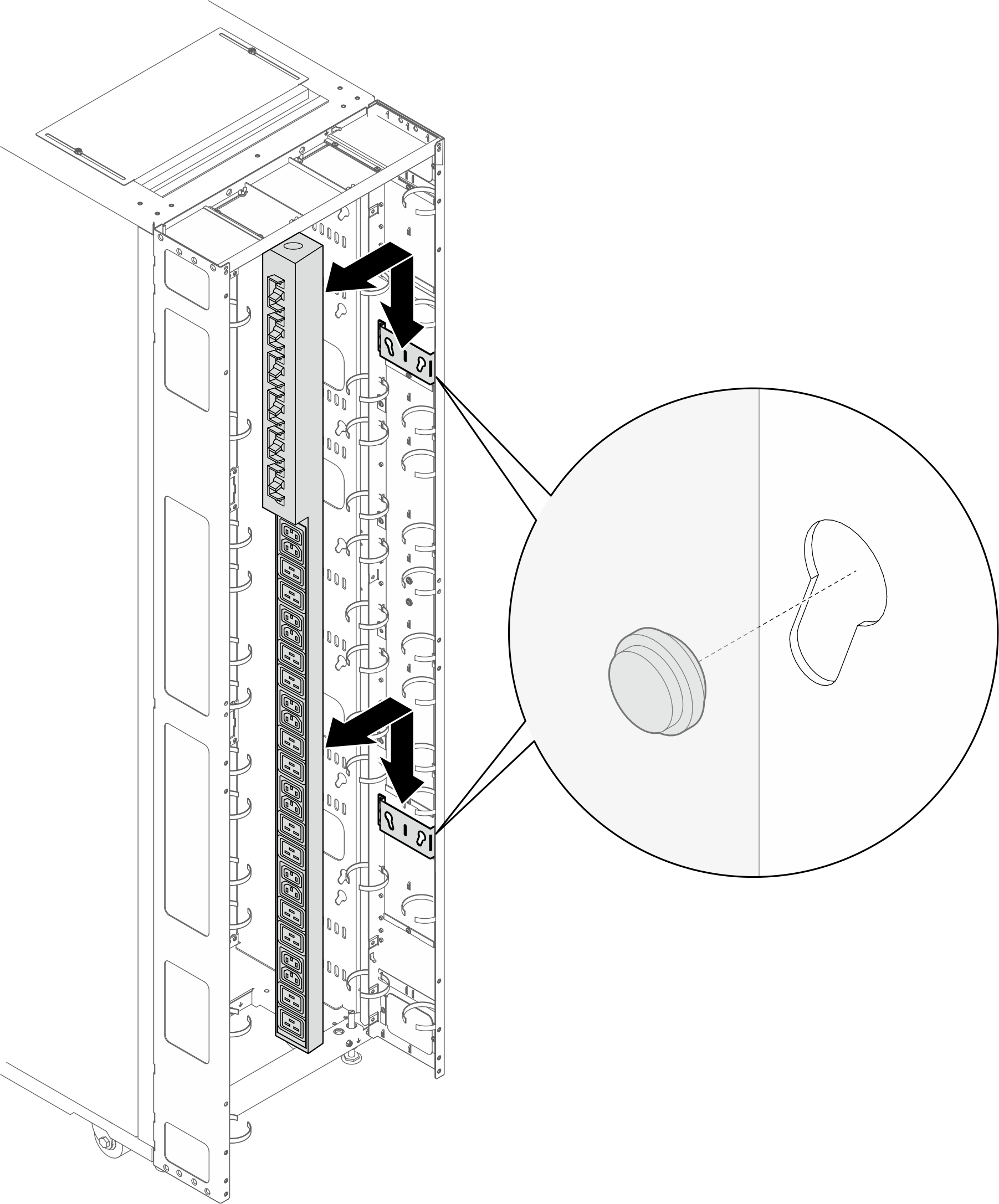 หมายเหตุPDU สามารถหมุนได้ 180 องศาสำหรับการติดตั้งด้วยสายอินพุตที่ด้านล่าง
- ภาพประกอบด้านล่างแสดงตำแหน่งสำหรับติดตั้งโครงยึด
- โครงยึดรูปตัว L (PDU สูงสุดสองตัว หรือ PDU หนึ่งตัวและท่อร่วมหนึ่งตัว)หมายเหตุ
- ภาพประกอบด้านล่างแสดงตำแหน่งสำหรับติดตั้งโครงยึดรูปที่ 15. ตำแหน่งสำหรับติดตั้งโครงยึดรูปตัว L
- หากมีการติดตั้งโครงยึดหนึ่งหรือสองตัวในตำแหน่งที่ระบุในภาพประกอบด้านล่าง จะต้องเปลี่ยนสกรูหน้าแปลนหัวหกเหลี่ยม M6 ด้วยสกรูหน้าแปลนหัวกลม M6รูปที่ 16. การเปลี่ยนสกรู
- ถอดสกรูหน้าแปลนหัวหกเหลี่ยม M6 ออก
- ติดตั้งสกรูหน้าแปลนหัวกลม M6
- จัดแนวโครงยึดให้ตรงกับแผงส่วนต่อขยาย และยึดให้แน่นด้วยสกรูสามตัว เลือกตำแหน่งการติดตั้งสำหรับโครงยึดตามการวางแนวของ PDUรูปที่ 17. การติดตั้งโครงยึดรูปตัว L โดยให้ PDU หันเข้าหาด้านหน้าของตู้แร็ค
 รูปที่ 18. การติดตั้งโครงยึดรูปตัว L โดยให้ PDU หันเข้าหาด้านหน้าของตู้แร็ค
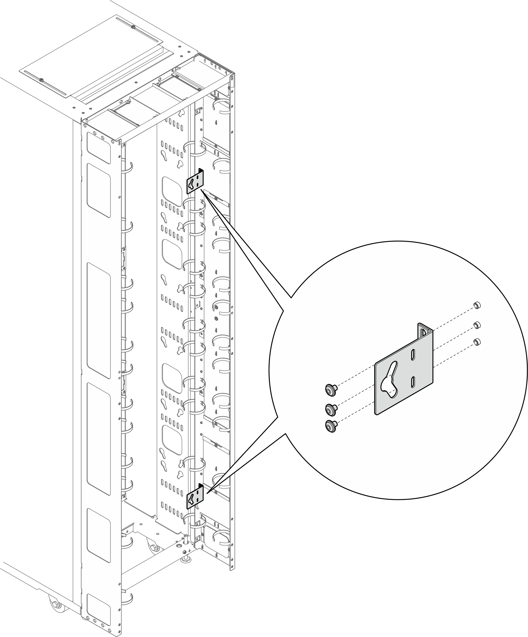
- ใส่หมุด PDU สองตัวลงในช่องรูกุญแจบนโครงยึด แล้วกด PDU ลงเพื่อยึดเข้ากับโครงยึดรูปที่ 19. การติดตั้ง PDU โดยให้ PDU หันหน้าไปทางด้านหน้าของตู้แร็ค
 รูปที่ 20. การติดตั้ง PDU โดยให้ PDU หันไปทางด้านหลังของตู้แร็ค
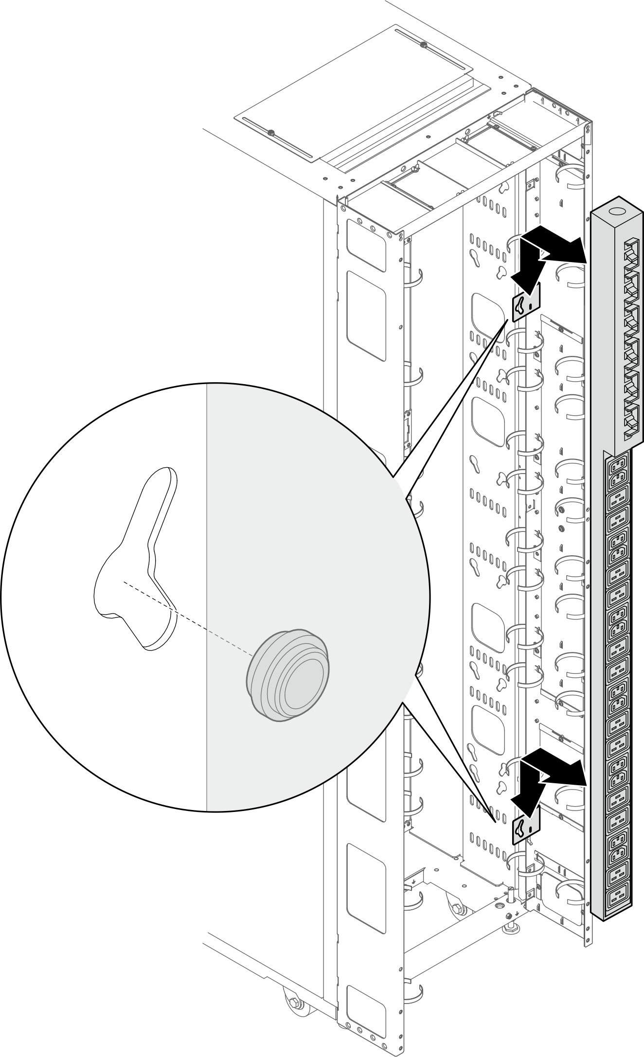
- ภาพประกอบด้านล่างแสดงตำแหน่งสำหรับติดตั้งโครงยึด
- เลือกวิธีใดวิธีหนึ่งต่อไปนี้เพื่อให้แน่ใจว่ามีพื้นที่เพียงพอสำหรับการเดินสาย โดยขึ้นอยู่กับข้อกำหนด
เลื่อนแผงแปรง
รูปที่ 21. การเลื่อนแผงแปรง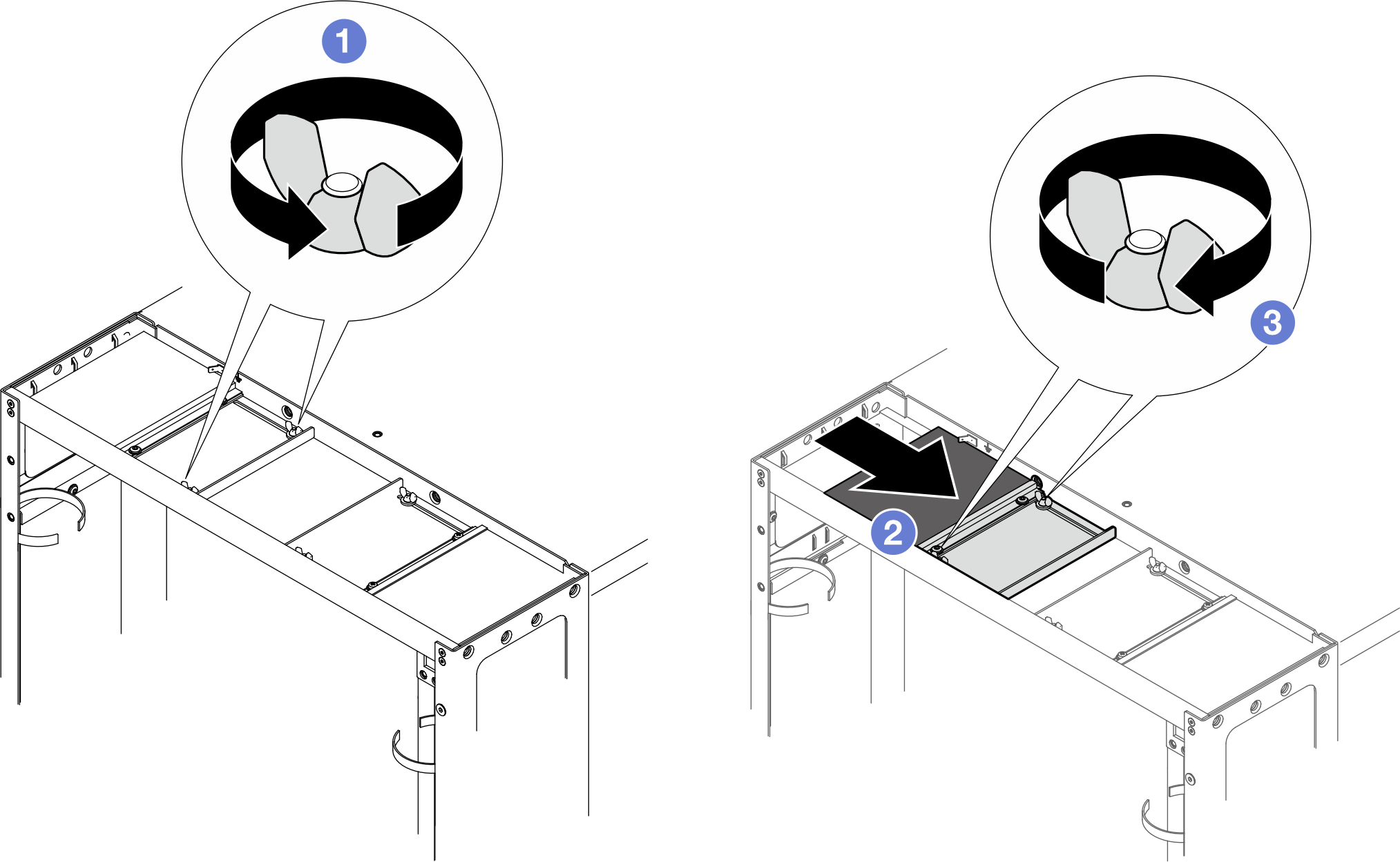
- คลายสกรูสองตัวที่ยึดแผ่นกั้นเข้ากับฝาครอบด้านบน
- เลื่อนแผ่นกั้นและแผงแปรงไปทางกึ่งกลางของฝาครอบด้านบน
- ขันสกรูสองตัวให้แน่นเพื่อยึดแผ่นกั้น
ถอดแผงแปรงออก
รูปที่ 22. การถอดแผงแปรง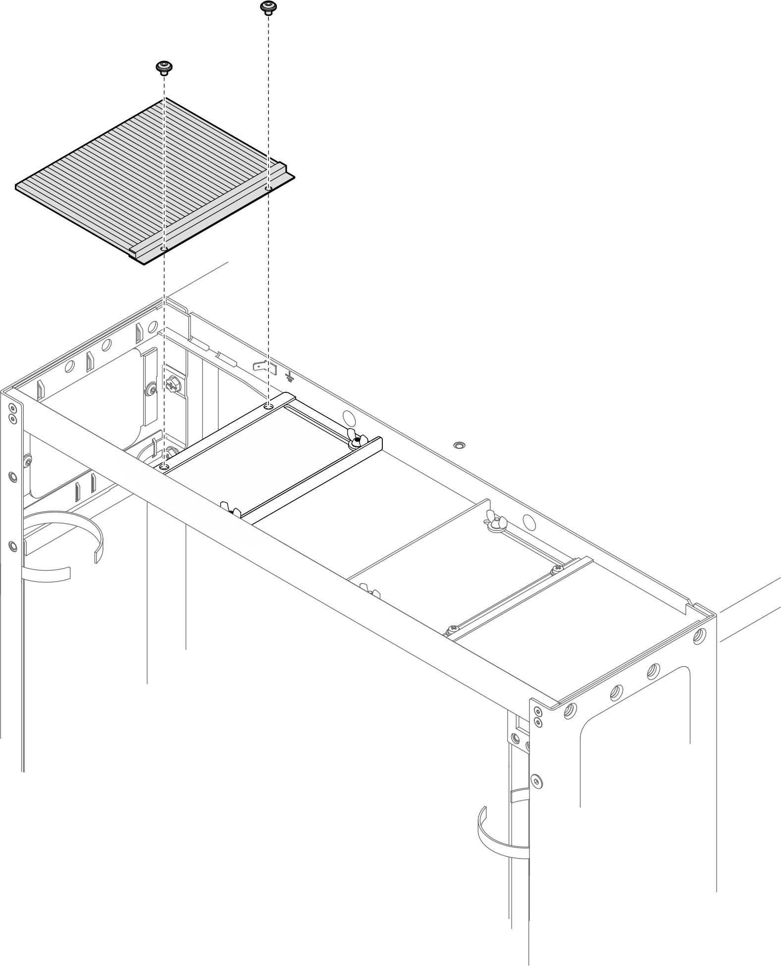
คลายสกรูสองตัวเพื่อถอดแผงแปรงออกจากฝาครอบด้านบน
ถอดแผงแปรงและแผ่นกั้นออก
รูปที่ 23. การถอดแผงแปรงและแผ่นกั้น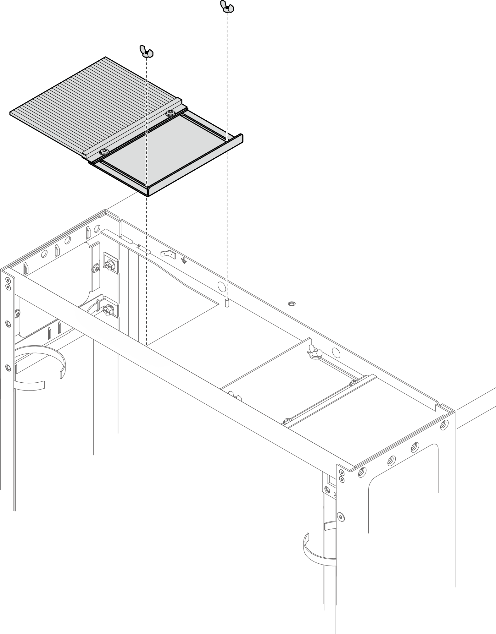
คลายสกรูสองตัวเพื่อถอดแผงแปรงและแผ่นกั้นออกจากฝาครอบด้านบน
- ขันสกรูสองตัวเพื่อยึดแผ่นสลักเข้ากับแผงต่อขยายด้านซ้ายรูปที่ 24. การติดตั้งแผ่นสลัก
- ถอดตัวหยุดประตูทั้งสองออกจากแผงต่อขยายด้านขวารูปที่ 25. การถอดตัวหยุดประตู
- ยึดบานพับด้านล่างเข้ากับแผงส่วนต่อขยายด้านขวาด้วยสกรูสี่ตัวรูปที่ 26. การยึดบานพับด้านล่าง
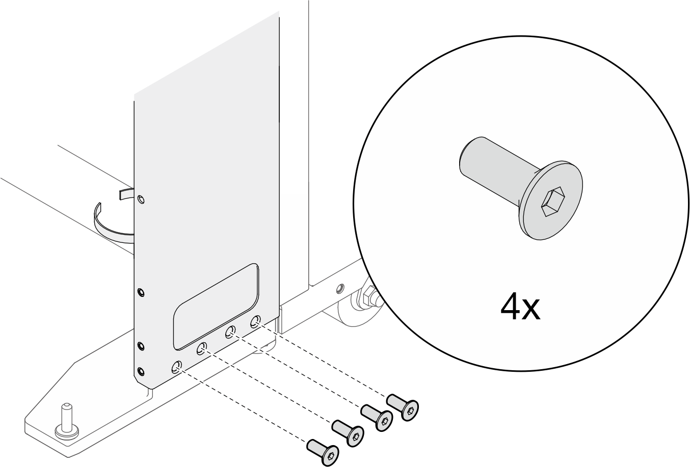
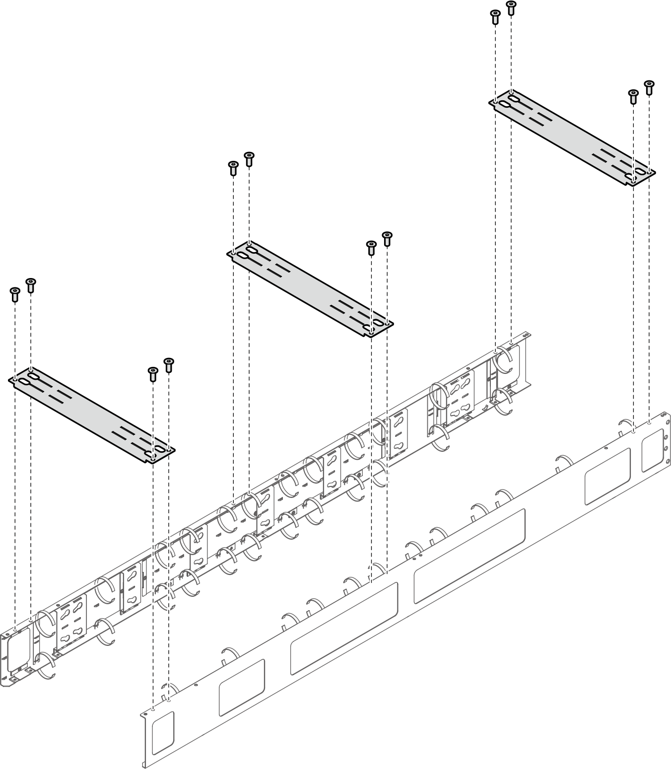
- หากจำเป็นต้องจัดส่งแร็ค ให้ติดตั้งโครงยึดรองรับสามตัวและข้ามขั้นตอนที่ 12 ถึง 17หมายเหตุต้องถอดโครงยึดรองรับออกเมื่อมาถึงสถานที่เพื่อติดตั้ง RDHXรูปที่ 27. การติดตั้งโครงยึดรองรับ
- หันหน้าไปทางด้านล่างของกล่อง ถอดด้านบนของกล่องออก และใช้มีดกรีดมุมกล่องทั้งสองข้างที่ด้านขวามือ จากนั้นพับแผงกล่องกระดาษด้านขวาลงมาที่พื้น และหมุนแผ่นกล่องกระดาษแข็งสามแผ่นลงรูปที่ 28. แกะกล่องแลกเปลี่ยนความร้อน
ด้านบน 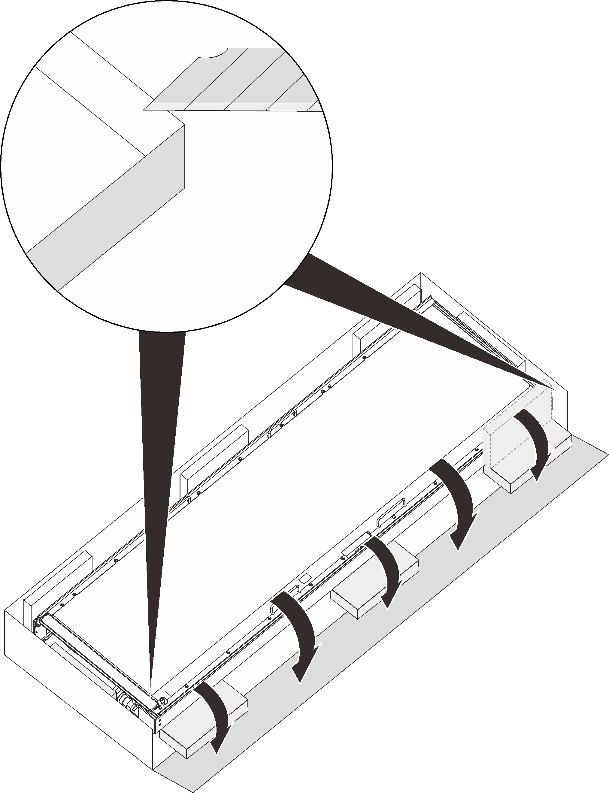
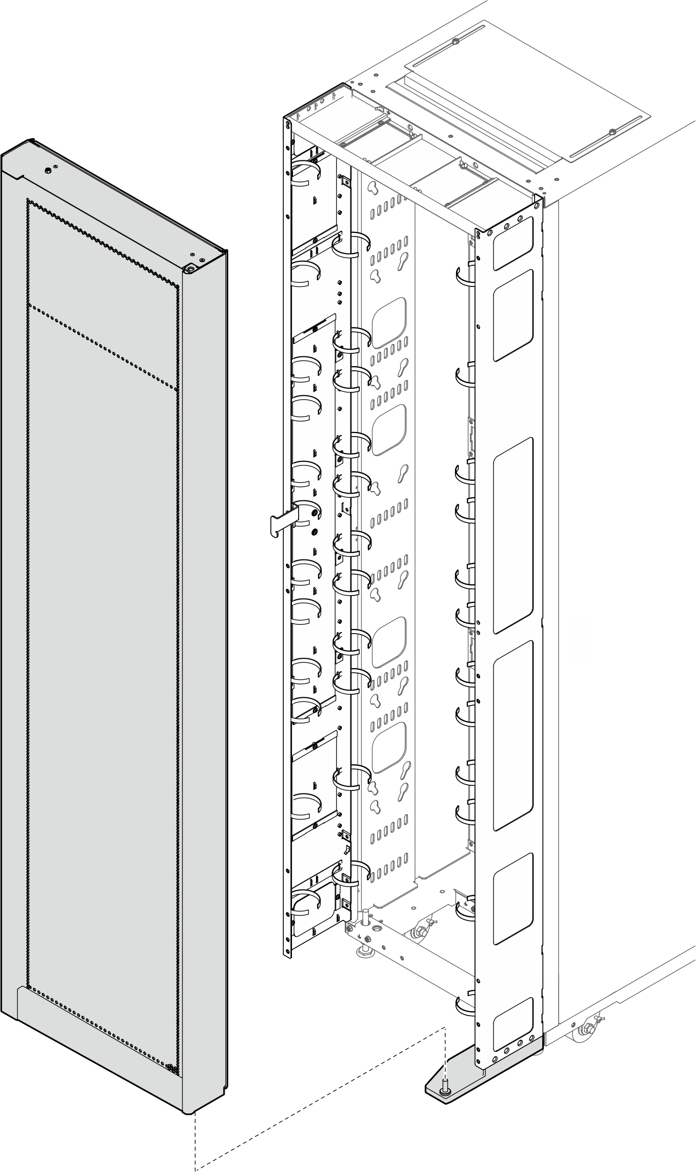
ด้านล่าง - ใช้คนสามคนหมุนตัวแลกเปลี่ยนความร้อนในแนวตั้งบนกล่องสามใบ จากนั้น ถอดแผงปิดท่อด้านในและด้านนอกออกในขณะที่คนหนึ่งถือตัวแลกเปลี่ยนความร้อนรูปที่ 29. การถอดแผงปิดท่อ
- จับตัวแลกเปลี่ยนความร้อนโดยให้คนสามคนจับที่จับ/จุดตามภาพ จากนั้นยกตัวแลกเปลี่ยนความร้อนขึ้นอย่างระมัดระวัง แล้วหมุนให้ตั้งตรงรูปที่ 30. การยกตัวแลกเปลี่ยนความร้อนด้วยคนสามคน
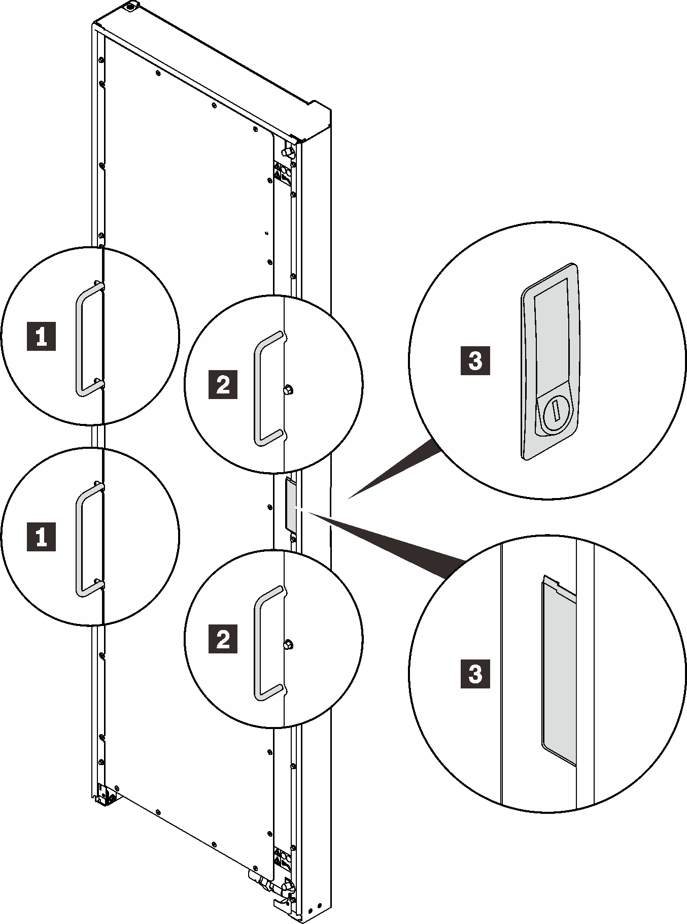
1 ที่จับซึ่งคนแรกยึดไว้ 3 จุดที่คนที่สามยึดไว้ 2 ที่จับซึ่งคนที่สองยึดไว้ - ยกตัวแลกเปลี่ยนความร้อนด้วยคนสามคนไปที่โครงตู้ จัดแนวมุมด้านล่างให้ตรงกับหมุดบานพับด้านล่าง จากนั้นลดตัวแลกเปลี่ยนความร้อนลงเพื่อให้พอดีกับหมุดรูปที่ 31. การติดตั้งตัวแลกเปลี่ยนความร้อนเข้ากับตู้แร็ค
- จับตัวแลกเปลี่ยนความร้อนให้อยู่กับที่โดยใช้คนสองคน ใส่หมุดบานพับด้านบนเข้ากับตัวแลกเปลี่ยนความร้อน จากนั้นยึดบานพับประตูด้วยสกรูเจ็ดตัวหมายเหตุอย่าขันสกรูเจ็ดตัวให้แน่นในขั้นตอนนี้รูปที่ 32. การติดตั้งบานพับด้านบน