48U Advanced Rack Extension Kit (RDHX 付き) の取り付け
48U Advanced Rack Extension Kit と RDHX の取り付け方法については、このトピックを参照してください。
ラック拡張キットの各ユニットには、ラックの両側に最大 2 個の 0U PDU、または 1 個の 0U PDU と 1 個の多岐管を収納できる追加容量が付属しています。
各ラック・キャビネットは、最大 2 つのラック拡張キット (前面に 1 つ、背面に 1 つ) をサポートします。
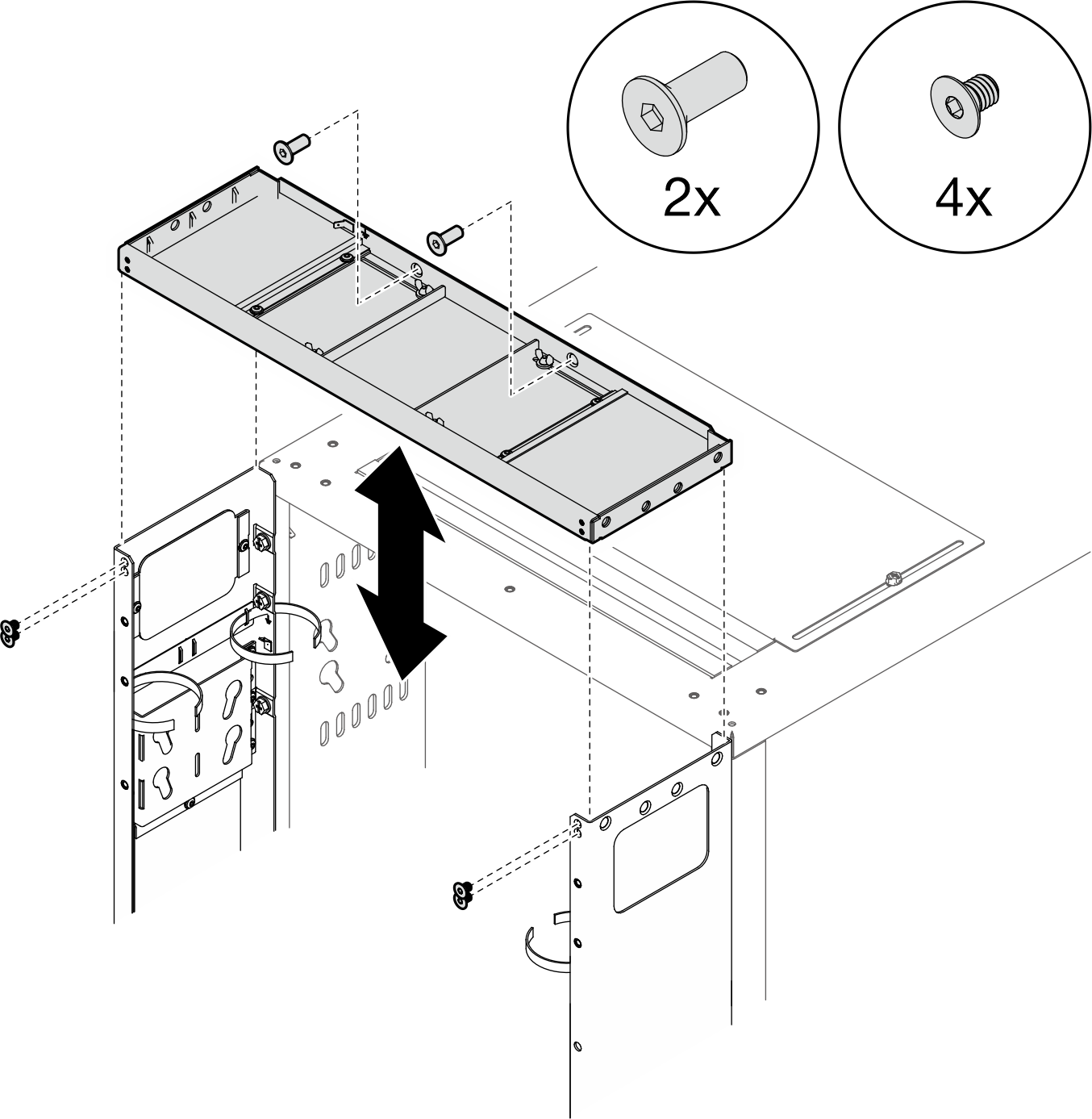
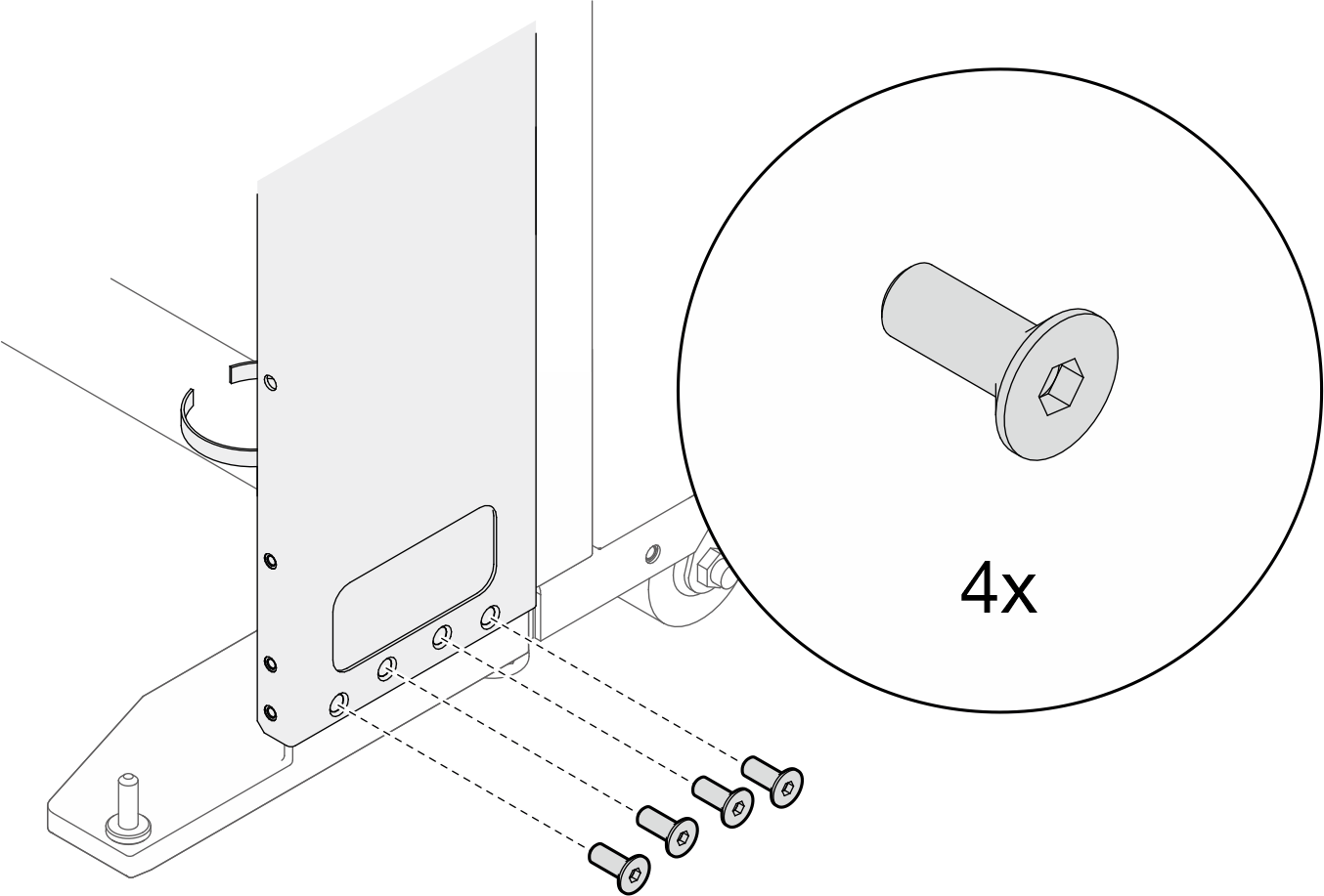
隣接するキャビネットの 1 つだけをエクステンション付きで取り付けるときにベイイング・キットを取り付ける計画がある場合は、必ずベイイング・キットを最初に取り付けてください (ベイイング・キットの取り付けを参照)。次に、この手順の準備として、ラック拡張キットを取り付けるキャビネットの上部と下部から 2 本のねじを取り外し、2に進みます。
図 1. 拡張取り付け準備のためのねじの取り外し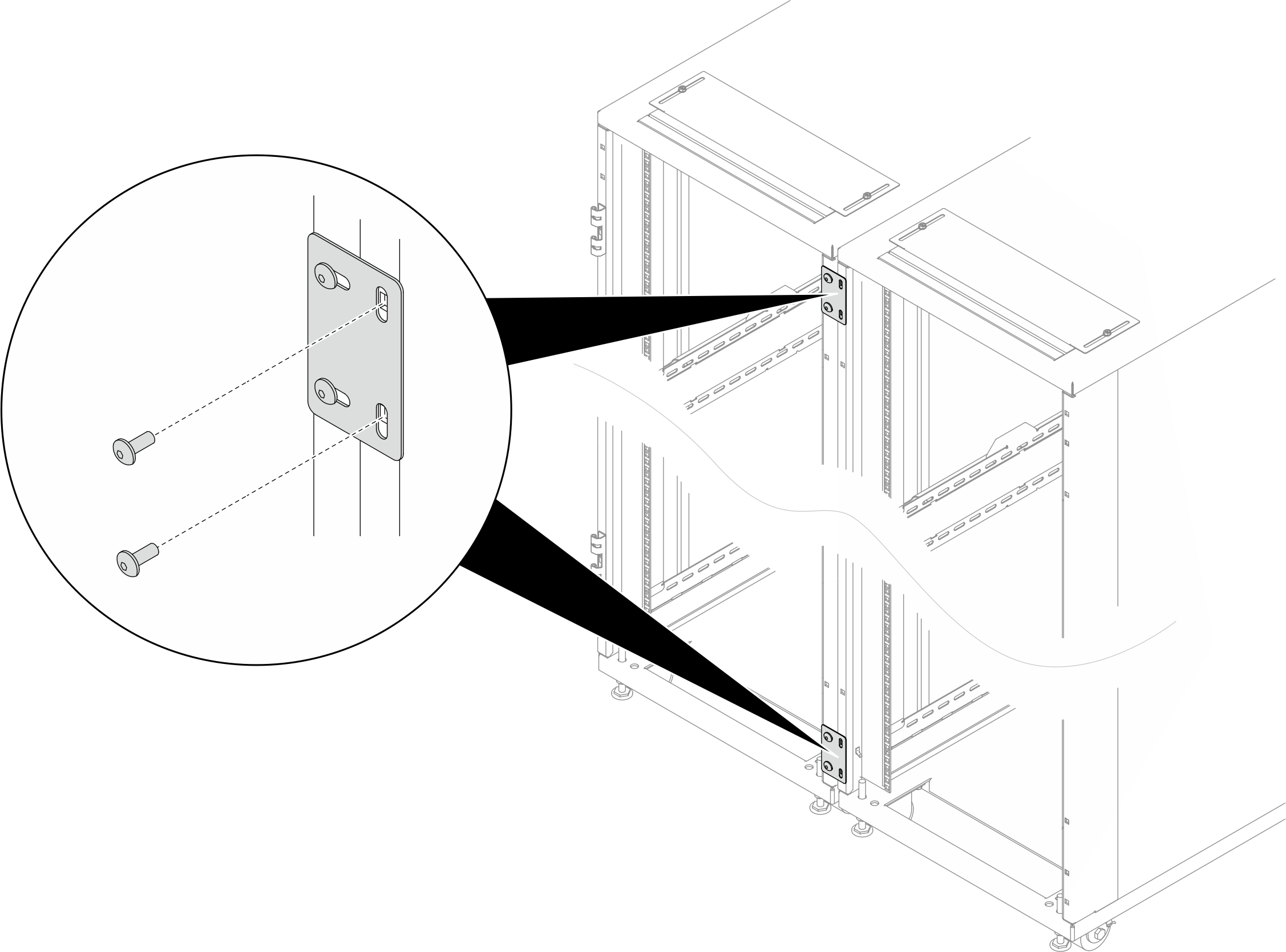
- 必要なツール
- パッケージを開梱するためのプラスチック製の刃/はさみが付いた工具 x 1
- 延長パネルをラックの側面に合わせるためのゴム製ハンマー x 1
- M6 ねじを締めるための No. 3 プラス・ビット付きドライバー x 1 (次の箇条書きの 9)
- M6 ねじを締めるための 10 mm 保持六角ビット付きナット・ドライバー x 1 (次の箇条書きの 9)
- M4 ねじを締めるための 2.5 mm 六角ビット・ソケット x 1 (次の箇条書きの 13)
- M5 ねじを締めるための 3 mm 六角ビット・ソケット x 1 (PDU/多岐管ブラケット、拡張パネルの開口部カバー)
- M6 ねじを締めるための 4 mm 六角ビット・ソケット x 1 (次の箇条書きの 4 および 14)
- 拡張キットには、以下のコンポーネントが追加の袋が付属しています。図 2. 部品
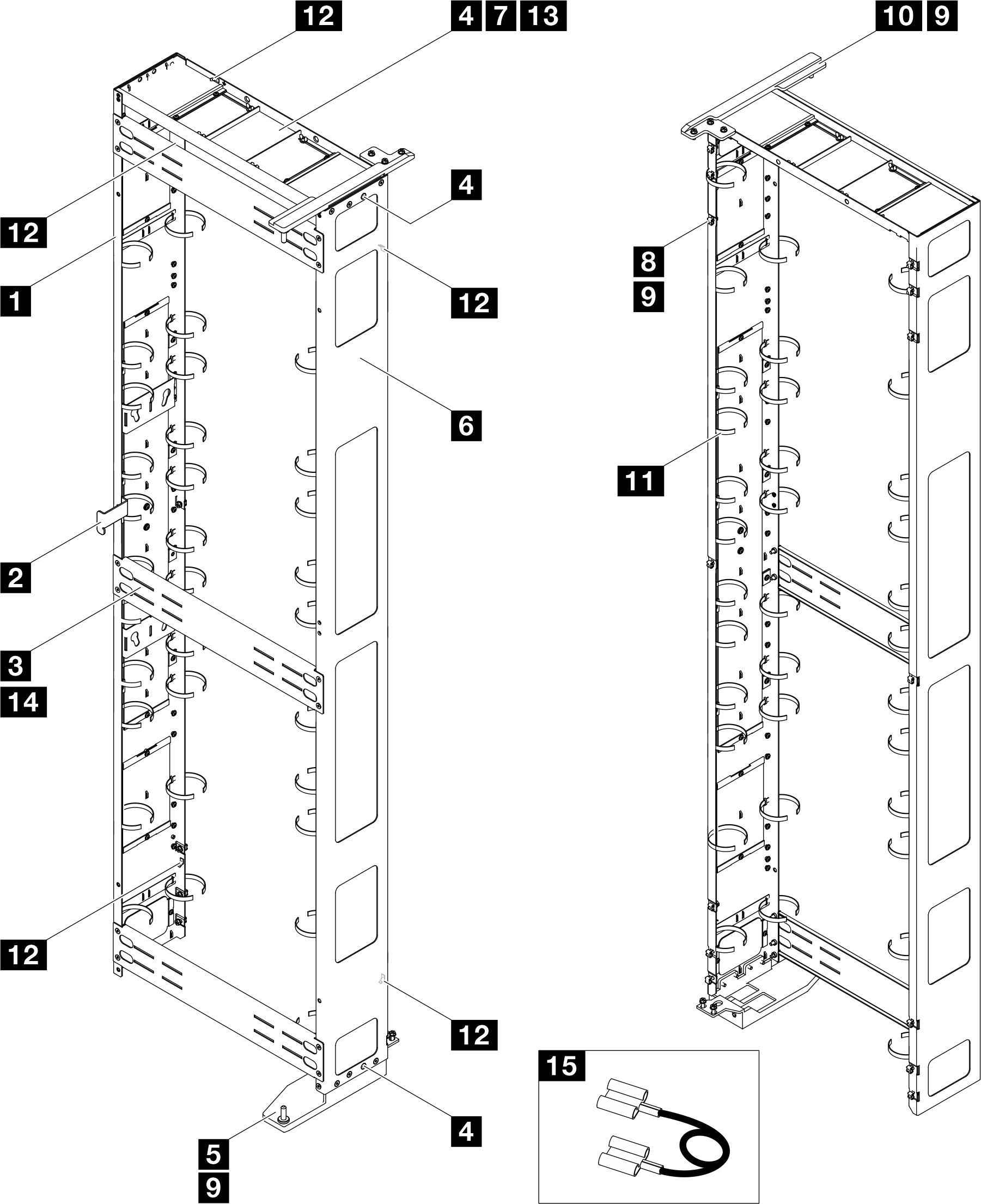
番号 説明 数量 番号 説明 数量 1 左側の拡張パネル 1 9 M6 x 16 mm 六角頭フランジねじ 21 2 ラッチ・プレート 1 10 RDHX 用上部ヒンジ 1 3 サポート・ブラケット 3 11 ケーブル・ストラップ・モジュール 123 2 4 M6 x 16 mm マイナス・ソケット・キャップねじ 10 12 接地プレート 5 5 RDHX 用下部ヒンジ 1 13 M4 x 6 mm マイナス・ソケット・キャップねじ 4 6 右側の拡張パネル 1 14 M6 x 12 mm マイナス・ソケット・キャップねじ 12 7 拡張トップ・カバー 1 15 接地線 4 3 8 M6 ケージ・ナット 14 - 1 ケーブル・ストラップは取り外し可能なため、必要に応じて拡張パネルからストラップを取り外してください。
- 2 ケーブル・ストラップは、2 本以上のストラップを接続して長くすることができます。
- 3 ケーブル・ストラップを使用して、出荷前に PDU および多岐管を固定します。
- 4 接地線の一方の端を延長パネルの接地プレートに接続し、もう一方の端をラックの最も近い接地プレートに接続します。
図 3. 六角アレン・レンチ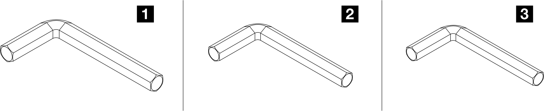
番号 説明 1 六角アレン・レンチ、4 mm 2 六角アレン・レンチ、3 mm 3 六角アレン・レンチ、2.5 mm
手順
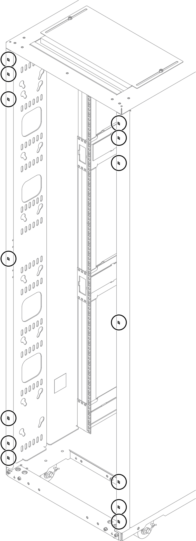
- ケージ・ナット挿入ツールまたはマイナス・ドライバーを使用して、ラック・フレームに 14 個の M6 ケージ・ナットを取り付けます。図 4. ケージ・ナットの設置場所
 ケージ・ナット差し込み工具を使用図 5. ケージ・ナット挿入ツールを使用したケージ・ナットの取り付け
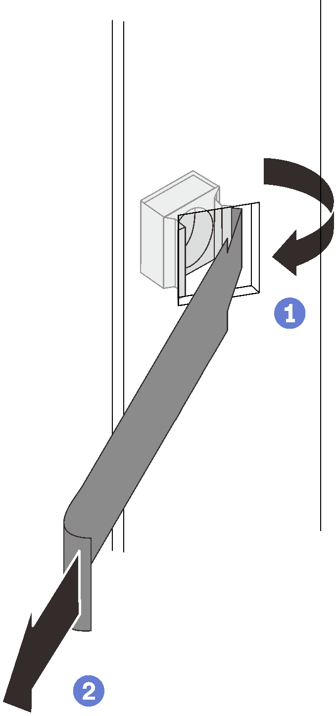
 ケージ・ナットの一方の端をターゲット取り付けフランジ穴に挿入し、もう一方の端をフランジ穴に挿入工具で引っ掛けます。
 ツールを回転させて引っ張り、ナットのもう一方の端をフランジの穴に押し込んで、ナットを固定します。
マイナス・ドライバーを使用図 6. マイナス・ドライバーを使用したケージ・ナットの取り付け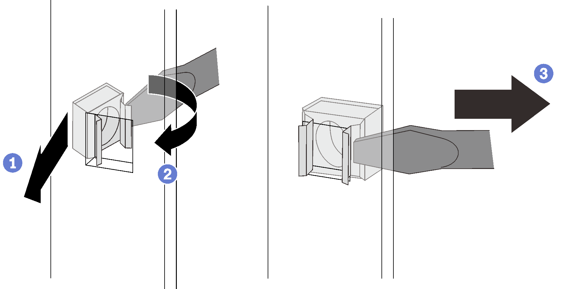
- ケージ・ナットの一方の端をターゲット取り付けフランジ穴に挿入します。
- もう一方のナットの端をマイナス・ドライバーで押して圧縮し、ナットの端が穴に入るまでドライバーをフランジの穴の方向に回転させます。
 ドライバーを放して、ナットを取り付けフランジの穴に固定します。
- 下部ヒンジを取り付けます。図 7. 下部ヒンジの固定
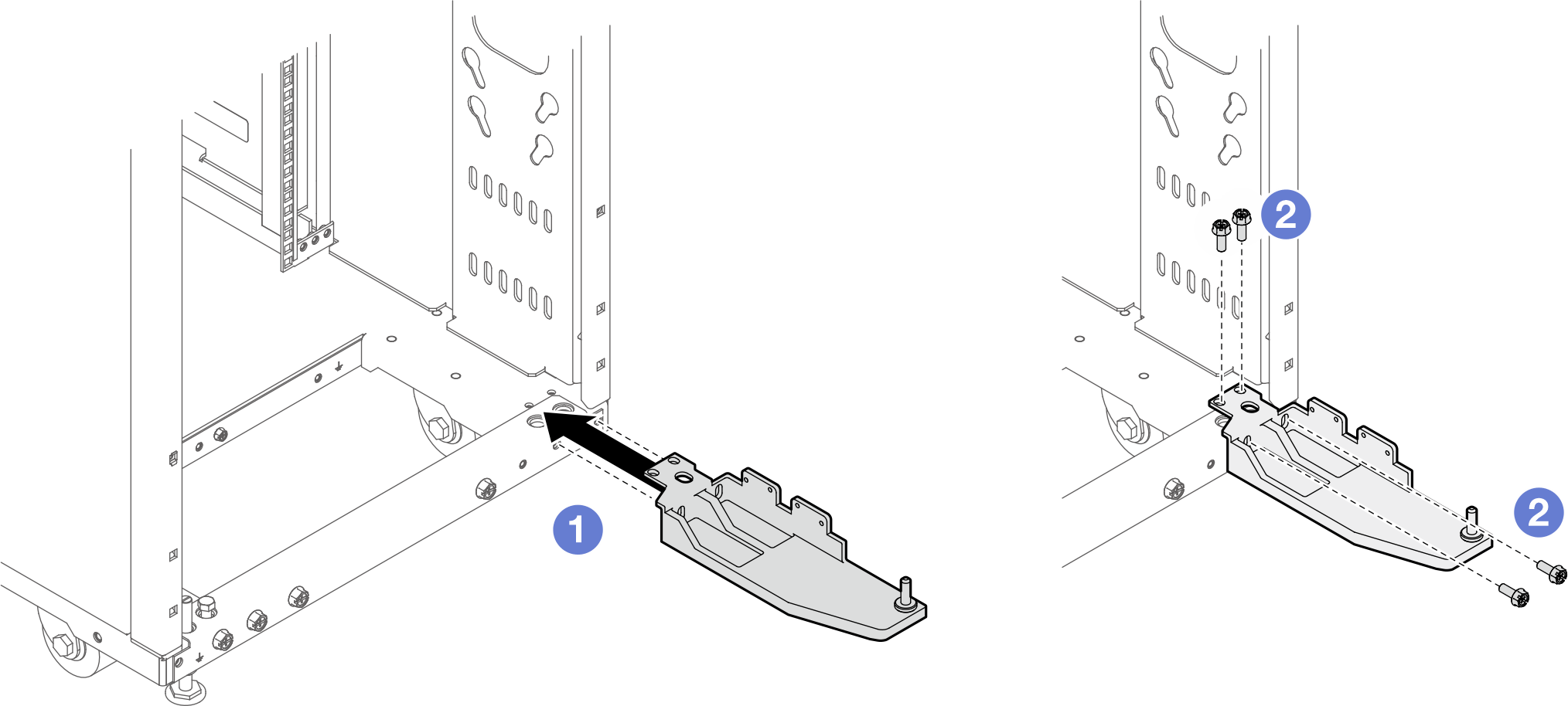 注このステップでは、4 本のねじを完全に締めないでください。
- ヒンジをラックに合わせます。
- 4 本のねじを使用してヒンジをラックに固定します。
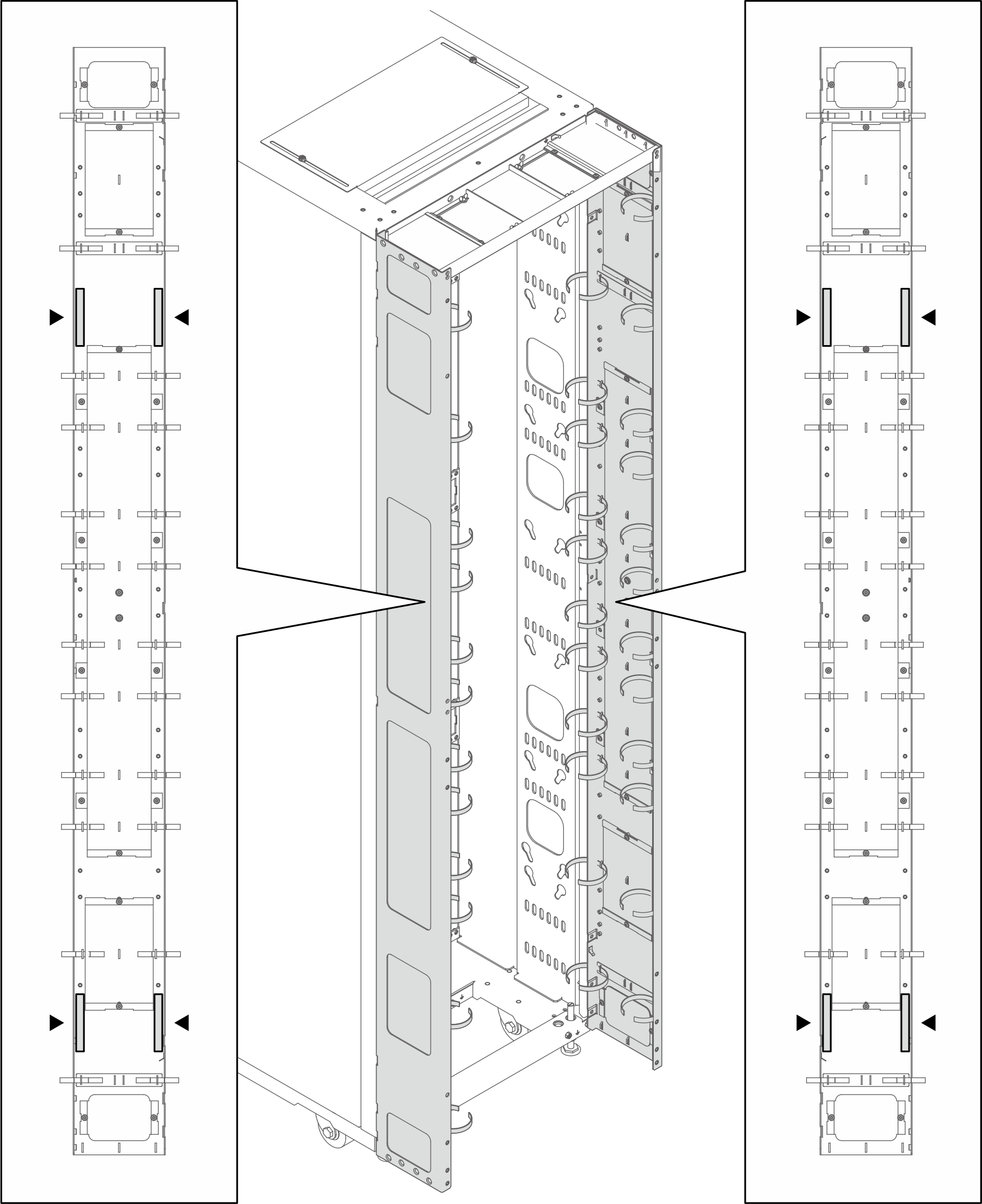
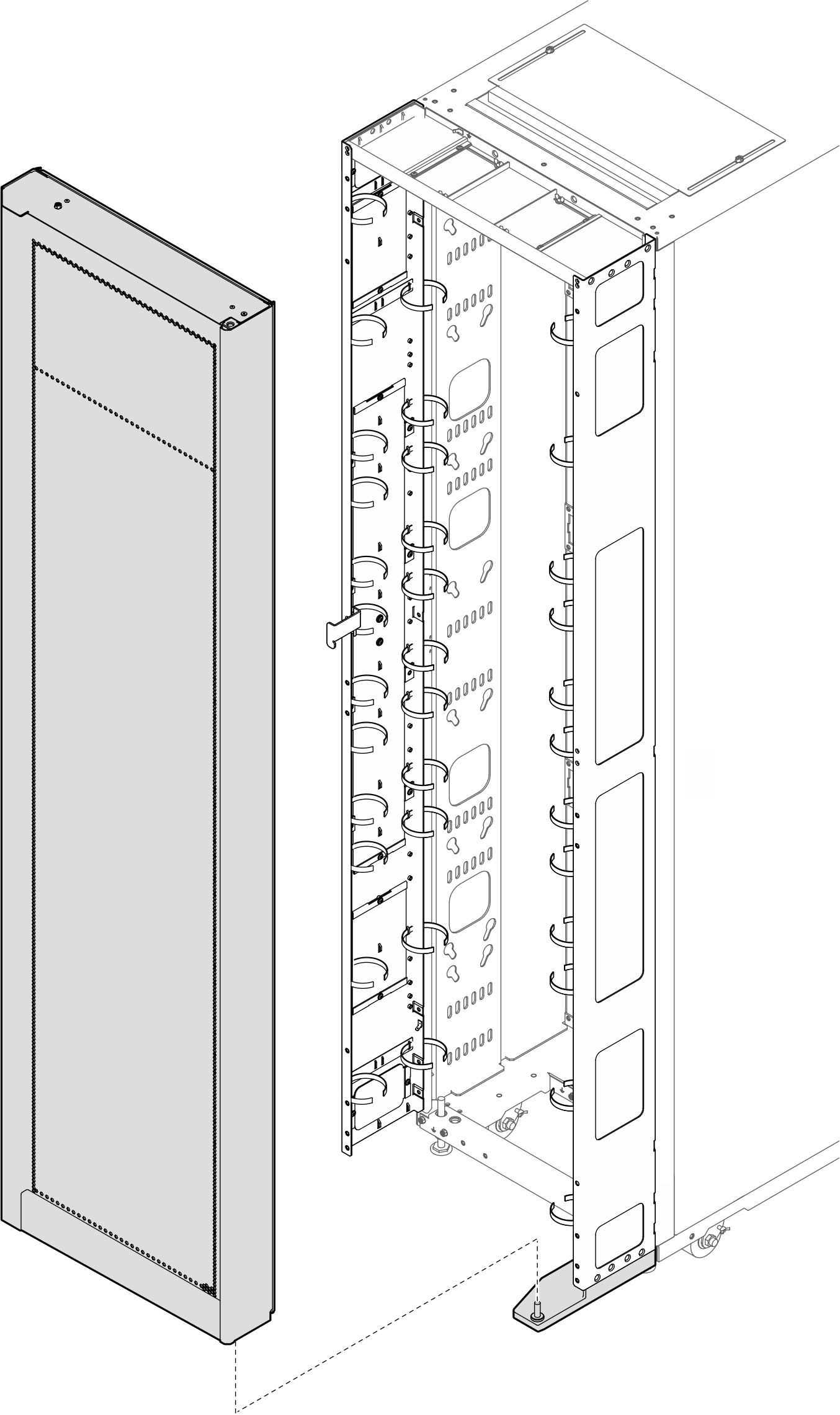
- 2 つの拡張パネルを 14 本のねじでラックに固定します。注
このステップでは、14 本のねじを完全に締めないでください。
ベイイング・キットを既に取り付けている場合、まずキャビネットの上部と下部から 2 本のねじを取り外してください。次に、パネルとベイイング・キットを通してねじを固定します。
図 8. 拡張パネルの取り付け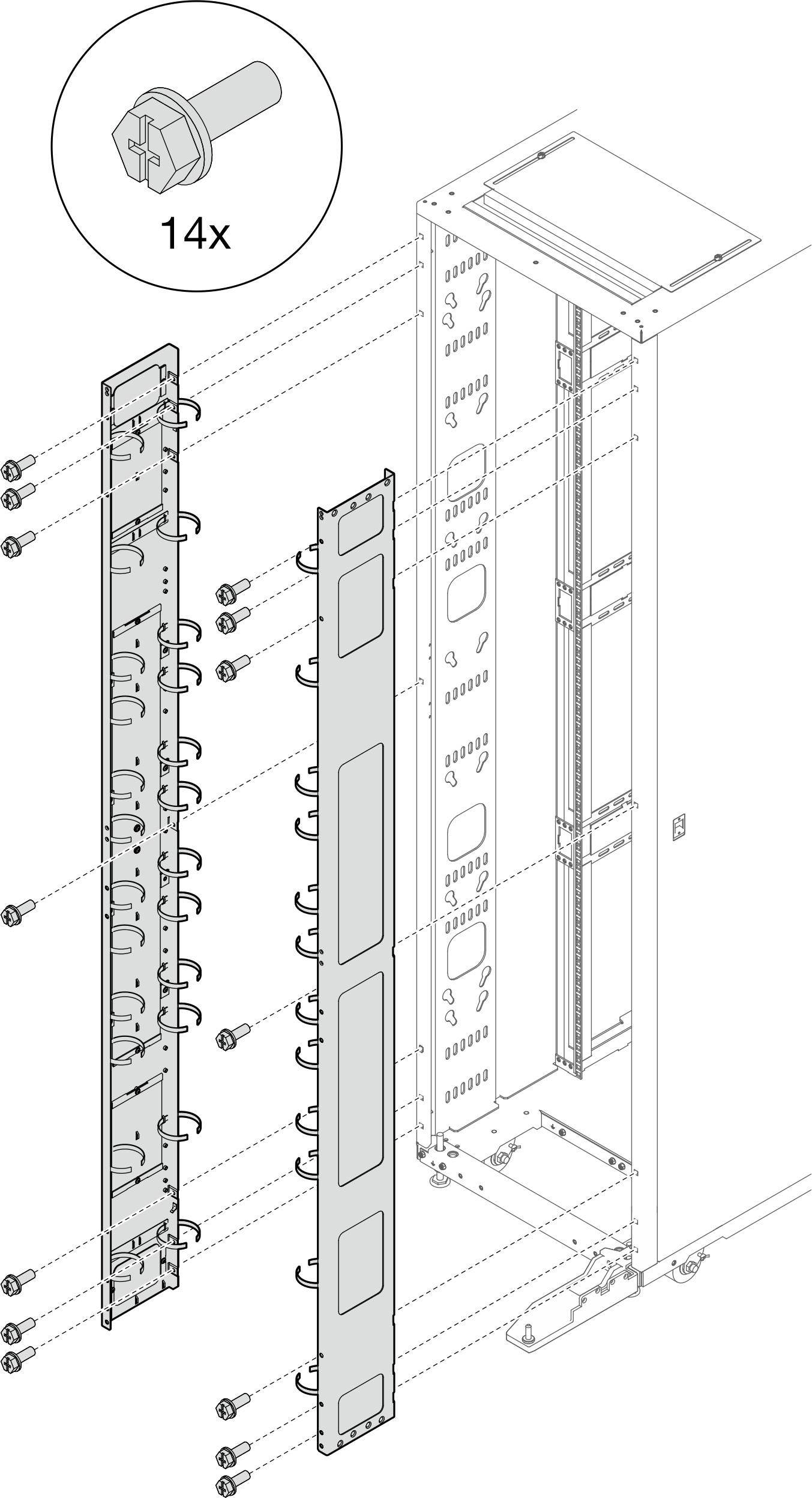
- 拡張トップ・カバーを拡張パネルのねじ穴に合わせ、6 本のねじで固定します。図 9. 拡張トップ・カバーの取り付け
- 要件に応じて、拡張パネルからフィラーを取り外してケーブルを配線します。図 10. フィラーの取り外し
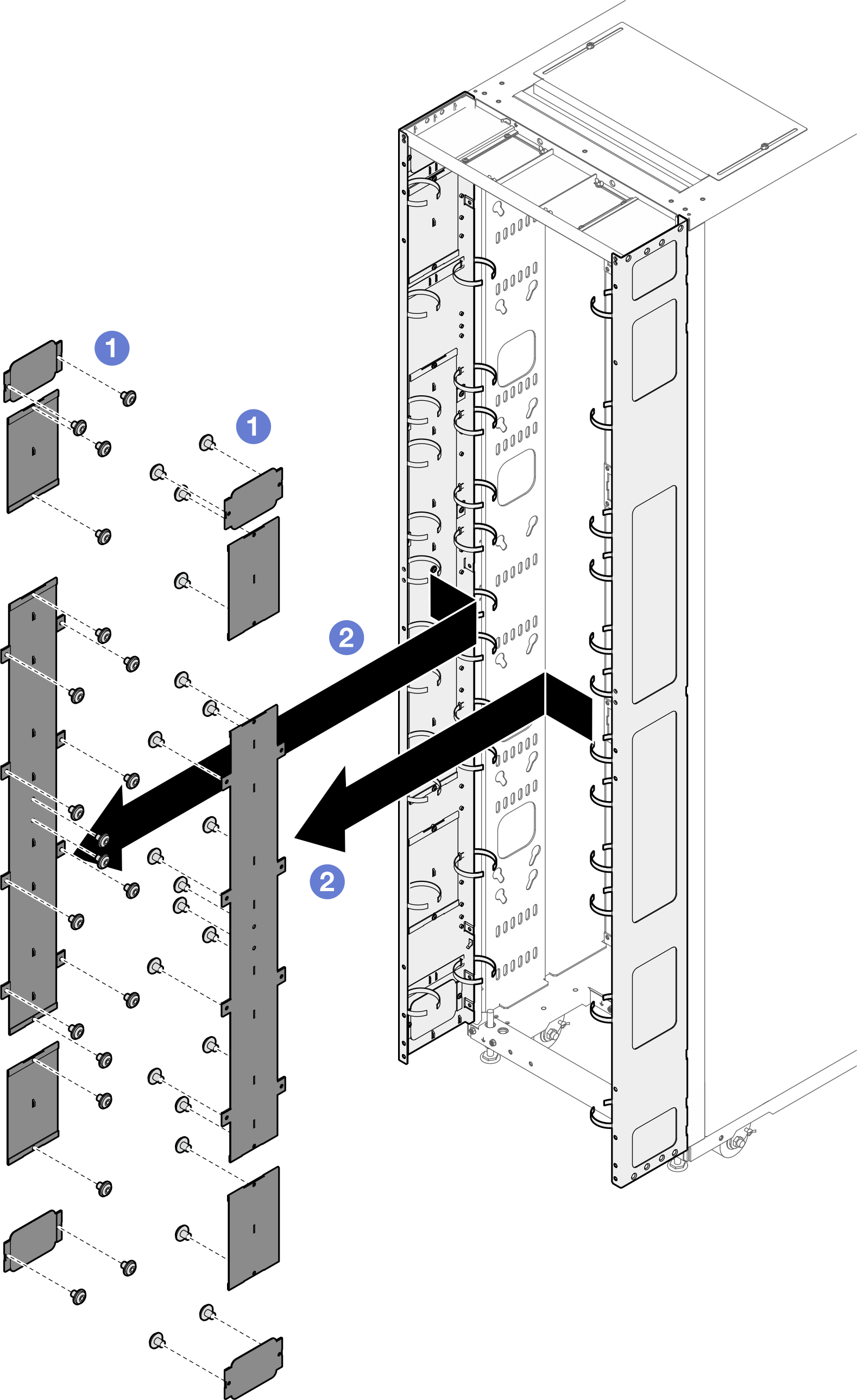
- フィラーを拡張パネルに固定しているねじを緩めます。
- フィラーを取り外します。
- 拡張パネルに 0U PDU を取り付ける計画がある場合は、以下のステップを実行します。要件に応じて、対応する取り付け手順を選択します。
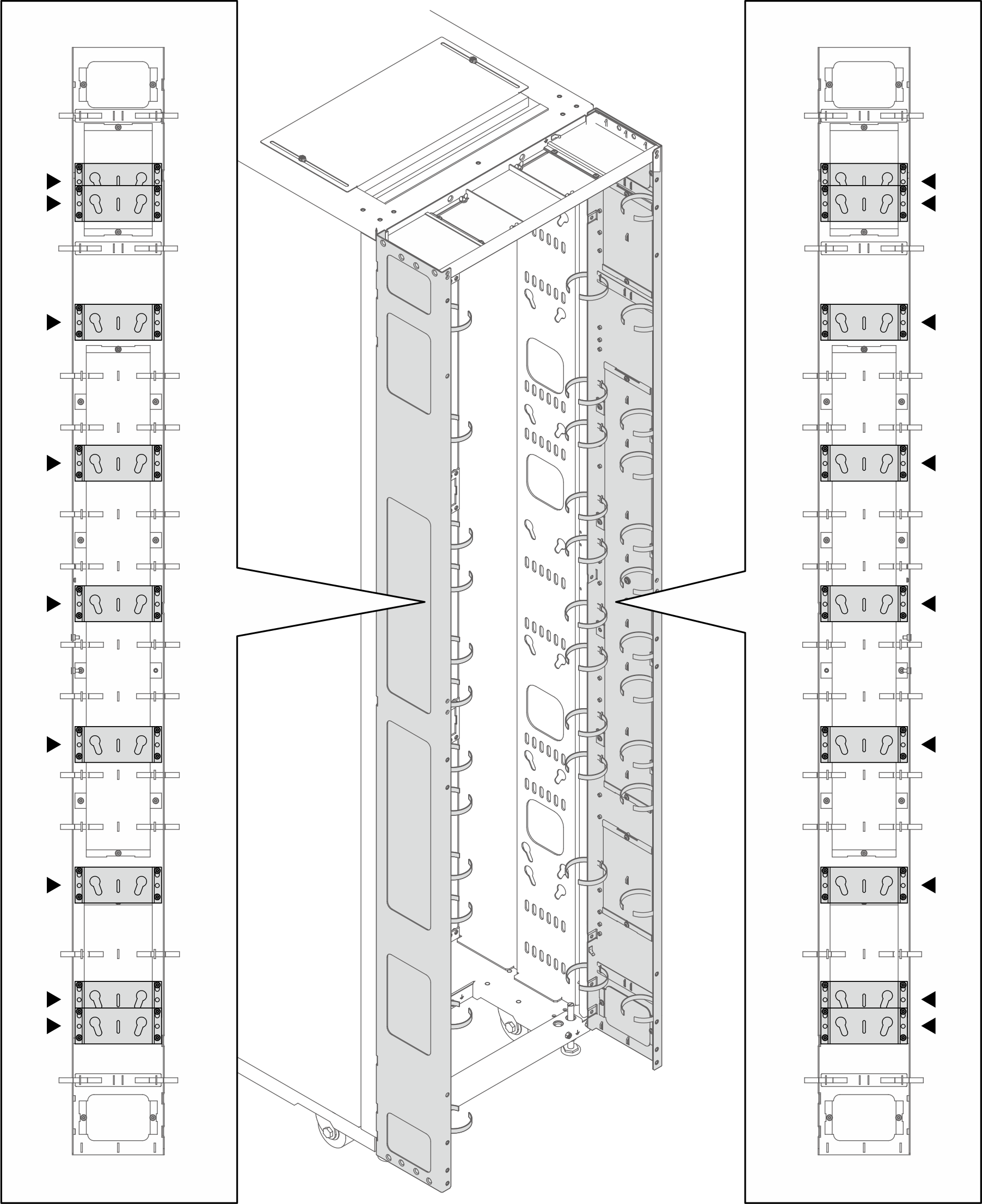
- 2 つの鍵穴スロット付きブラケット (最大 2 個の PDU、または 1 個の PDU と 1 個の多岐管)注
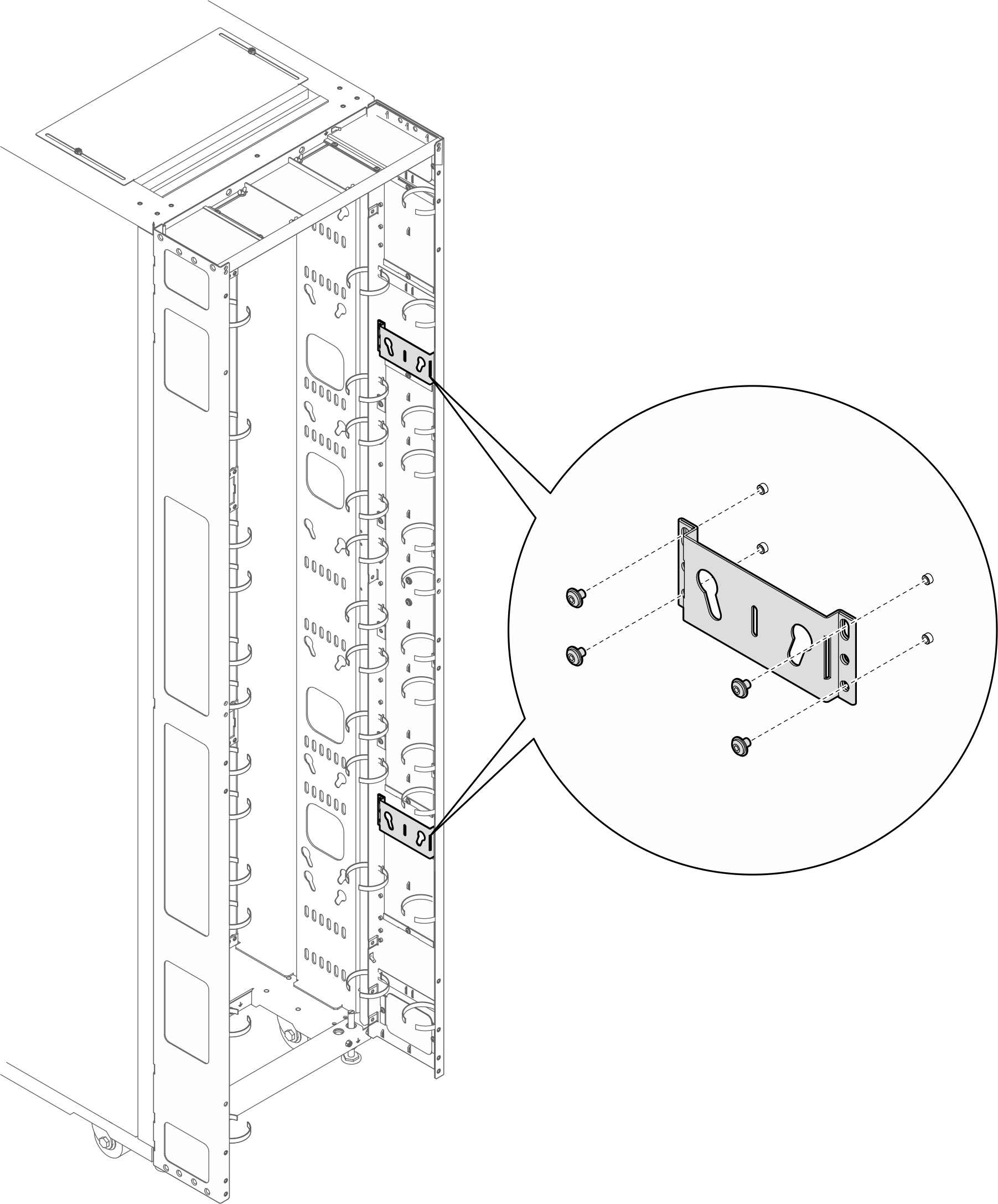
- 以下の図は、ブラケットを取り付ける位置を示しています。図 11. 2 つの鍵穴スロット付きブラケットの取り付け位置
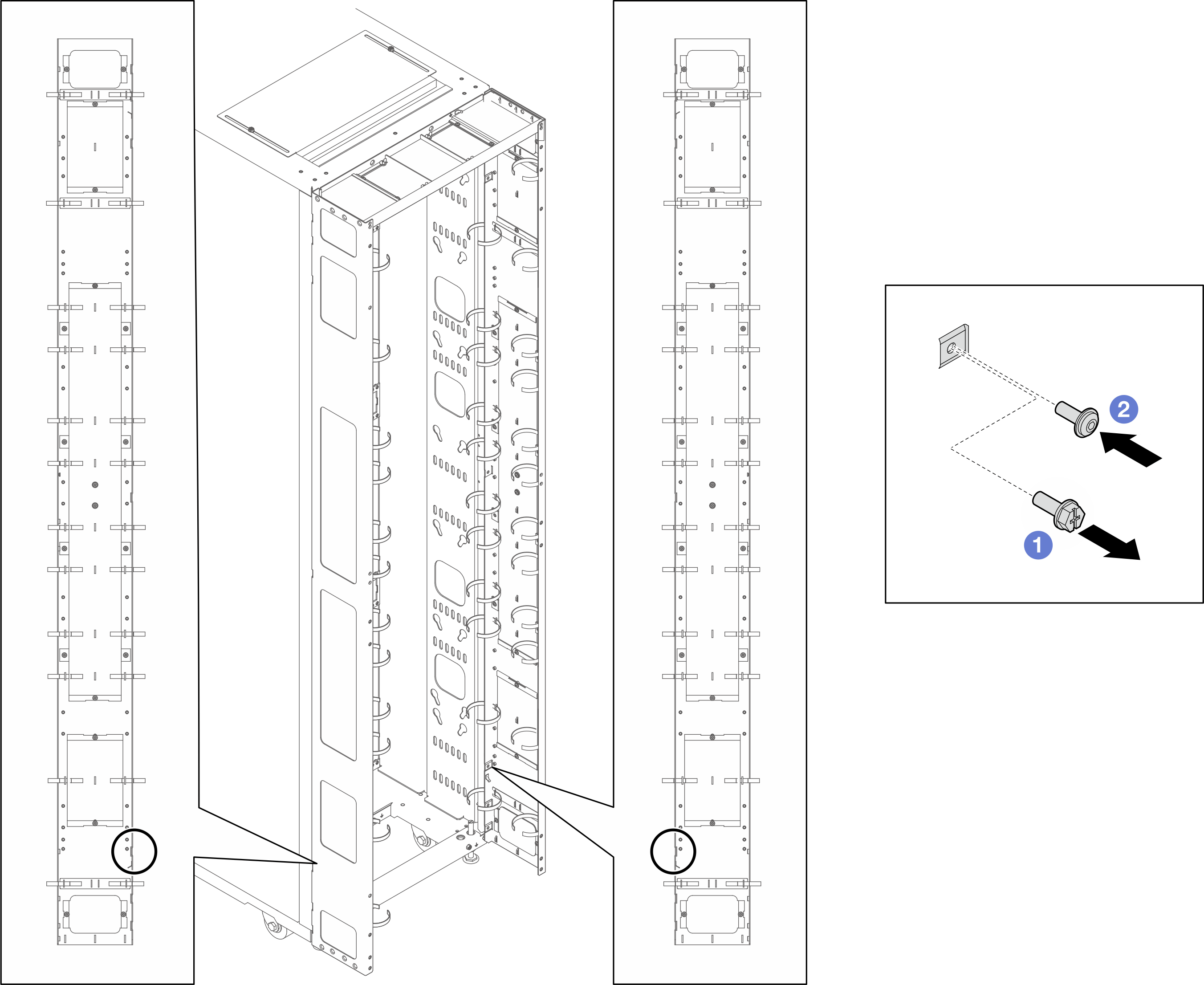
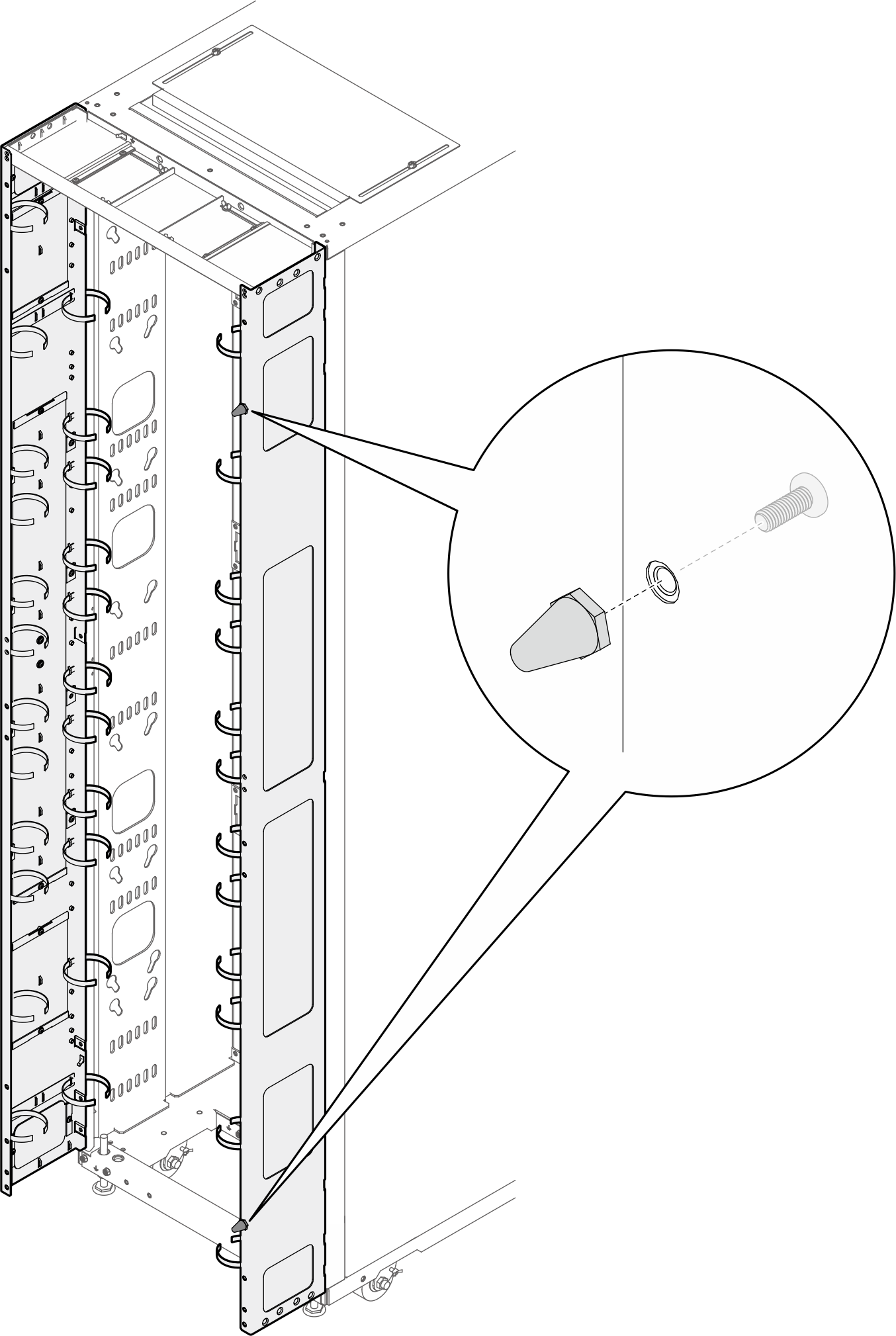
- 以下の図に示されている場所に 1 つまたは 2 つのブラケットが取り付けられている場合は、M6 六角頭フランジねじを M6 丸頭フランジねじに交換する必要があります。図 12. ねじの交換
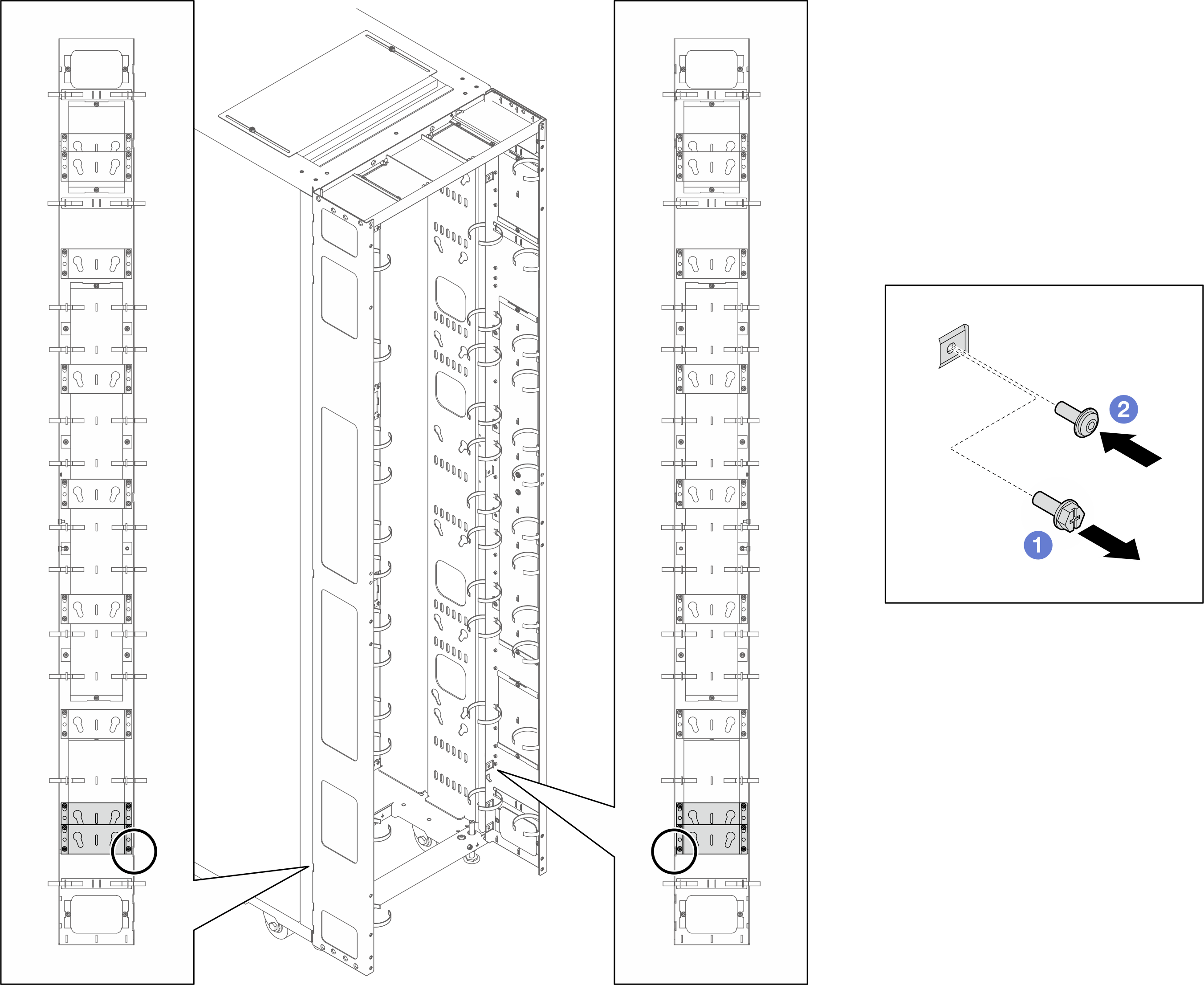
- M6 六角頭フランジねじを取り外します。
- M6 丸頭フランジねじを取り付けます。
- ブラケットを拡張パネルに位置合わせし、4 本のねじで固定します。図 13. 2 つの鍵穴スロット付きブラケットの取り付け
- 2 つの PDU ペグをブラケットの鍵穴スロットに挿入し、PDU を押し下げてブラケットに固定します。要件に基づいて、PDU 取り付け用の左スロットまたは右スロットを選択します。図 14. PDU の取り付け
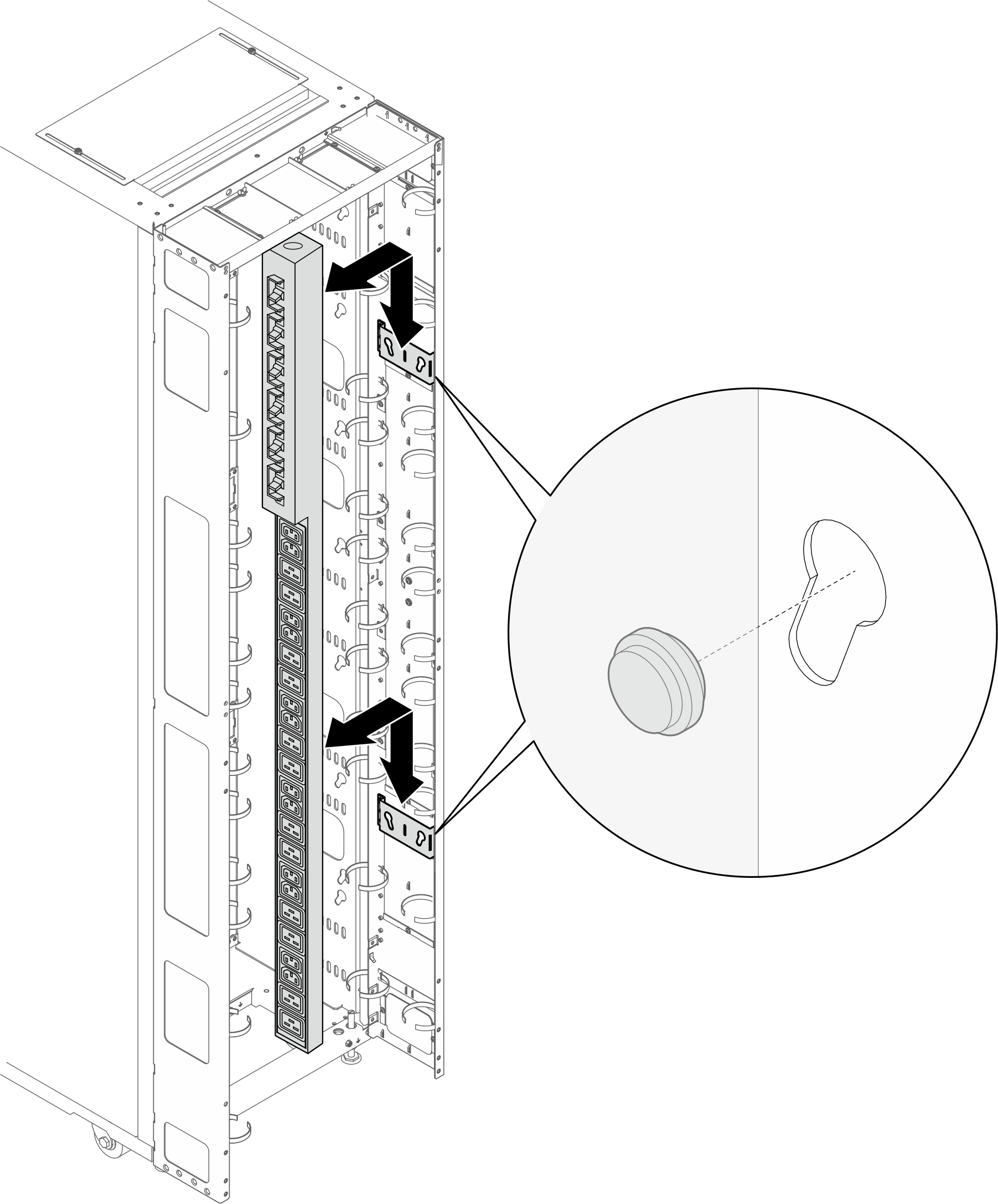 注PDU は 180 度回転させて、入力ケーブルが下部に来るよう取り付けることができます。
- 以下の図は、ブラケットを取り付ける位置を示しています。
- L 字型ブラケット (最大 2 つの PDU、または 1 つの PDU と 1 つの多岐管)注
- 以下の図は、ブラケットを取り付ける位置を示しています。図 15. L 字型ブラケットの取り付け位置
- 以下の図に示されている場所に 1 つまたは 2 つのブラケットが取り付けられている場合は、M6 六角頭フランジねじを M6 丸頭フランジねじに交換する必要があります。図 16. ねじの交換
- M6 六角頭フランジねじを取り外します。
- M6 丸頭フランジねじを取り付けます。
- ブラケットを拡張パネルに位置合わせし、3 本のねじで固定します。PDU の向きに基づいて、ブラケットの取り付け場所を選択します。図 17. PDU がラック・キャビネットの前面を向く状態での L 字型ブラケットの取り付け
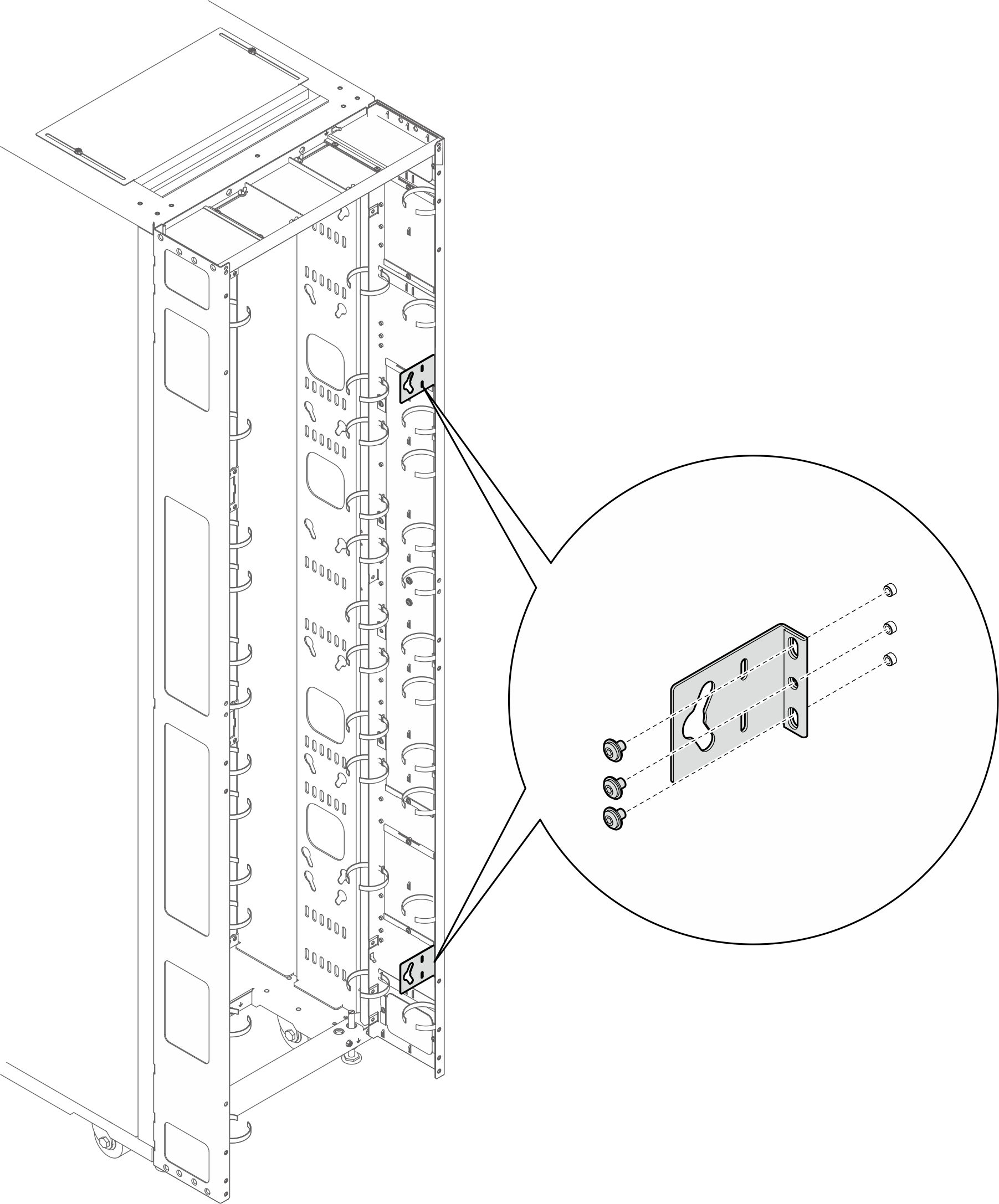 図 18. PDU がラック・キャビネットの前面を向く状態での L 字型ブラケットの取り付け
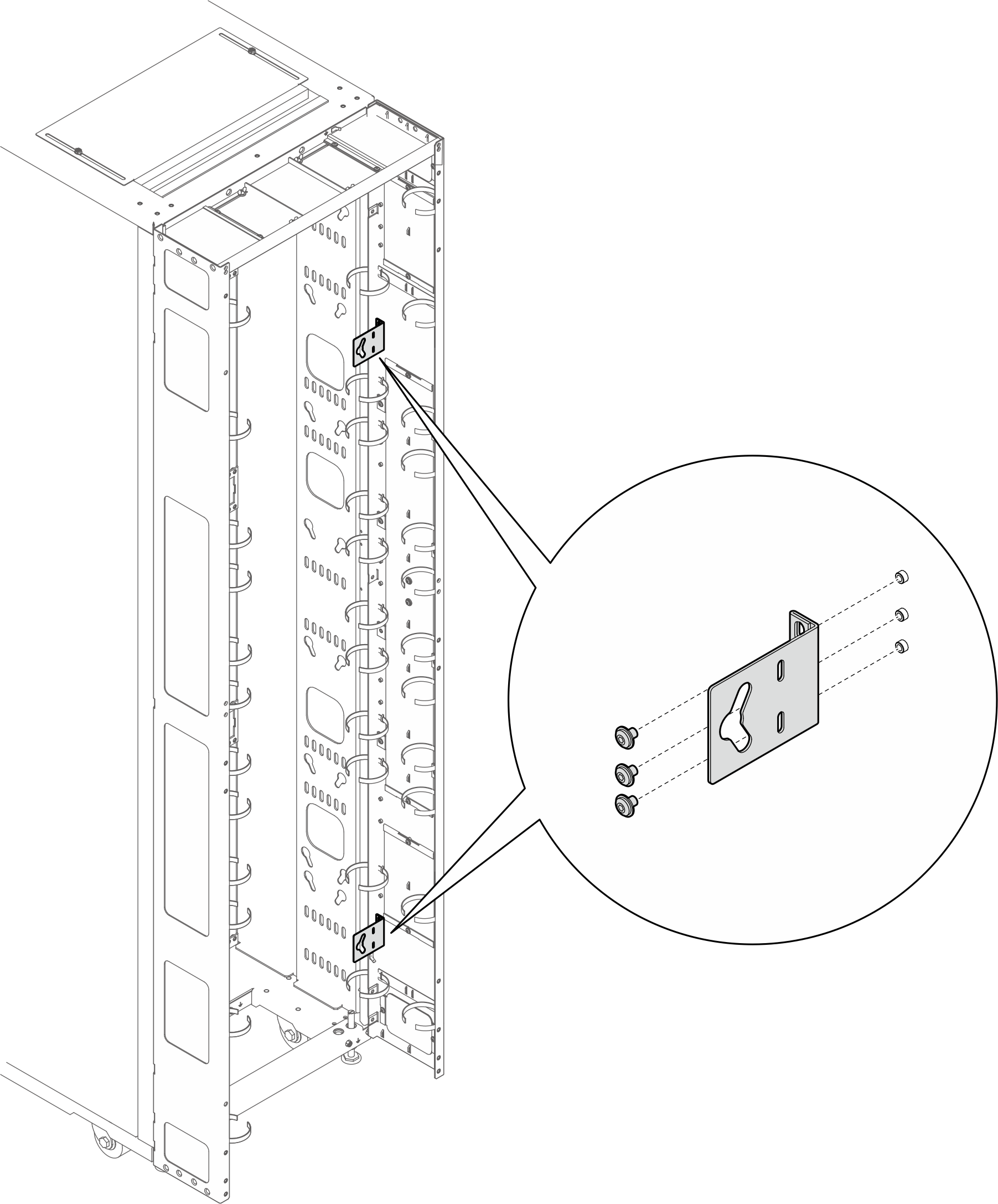
- 2 つの PDU ペグをブラケットの鍵穴スロットに挿入し、PDU を押し下げてブラケットに固定します。図 19. PDU がラック・キャビネットの前面を向いた状態での PDU の取り付け
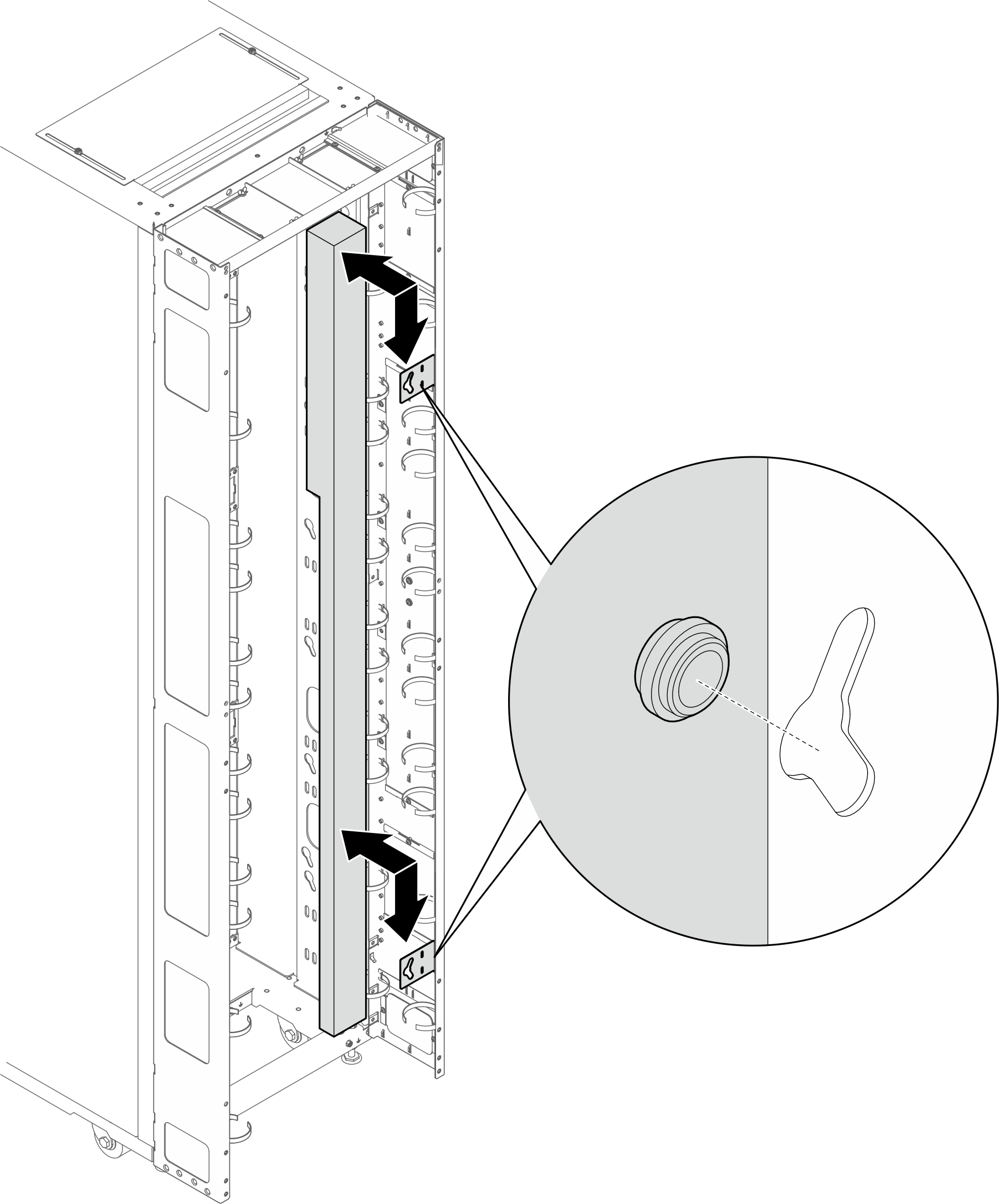 図 20. PDU がラック・キャビネットの背面を向いた状態での PDU の取り付け
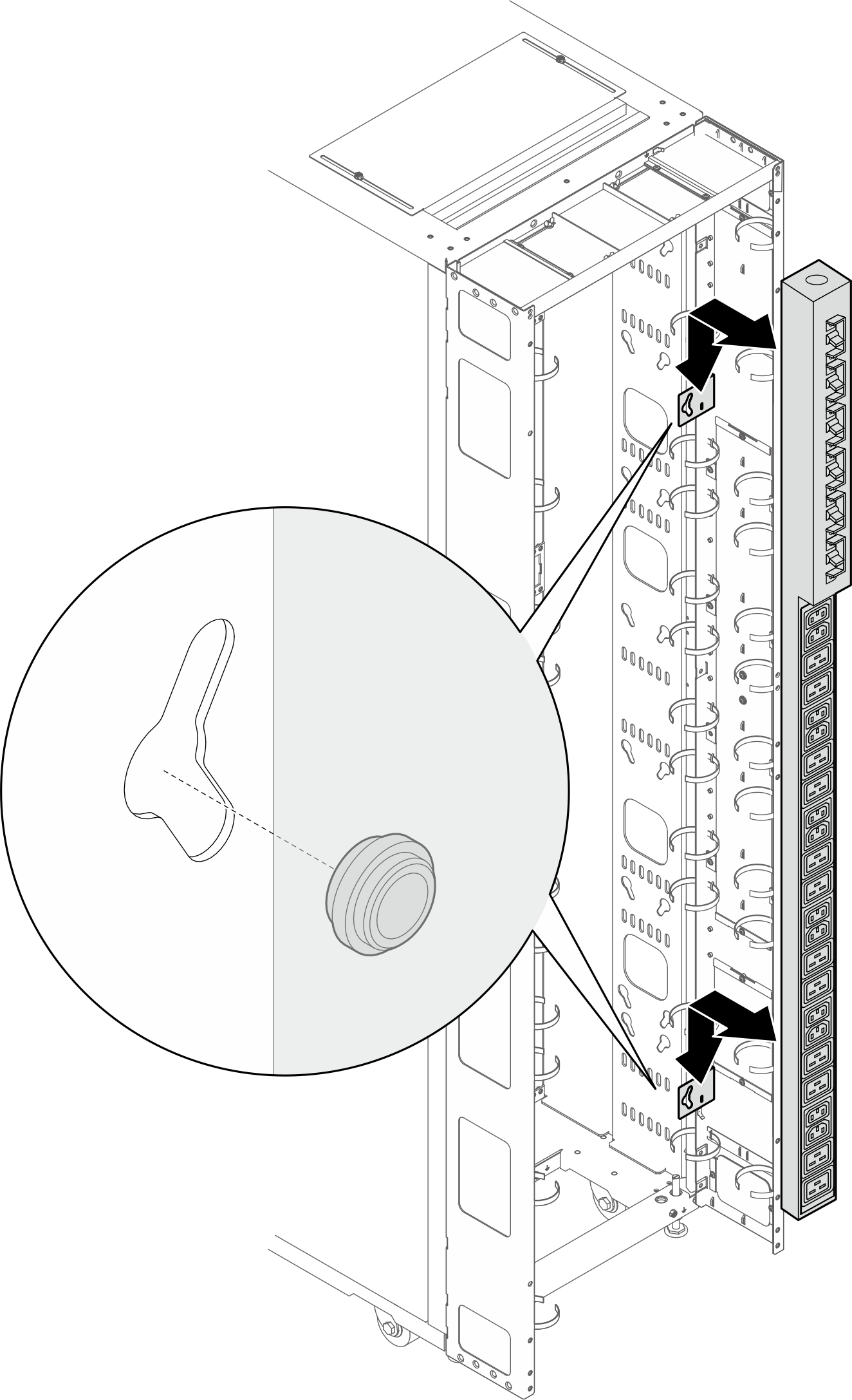
- 以下の図は、ブラケットを取り付ける位置を示しています。
- 要件に応じて、以下のいずれかの方法を選択し、ケーブルを配線するための十分なスペースを確保してください。
ブラシ・パネルのスライド
図 21. ブラシ・パネルのスライド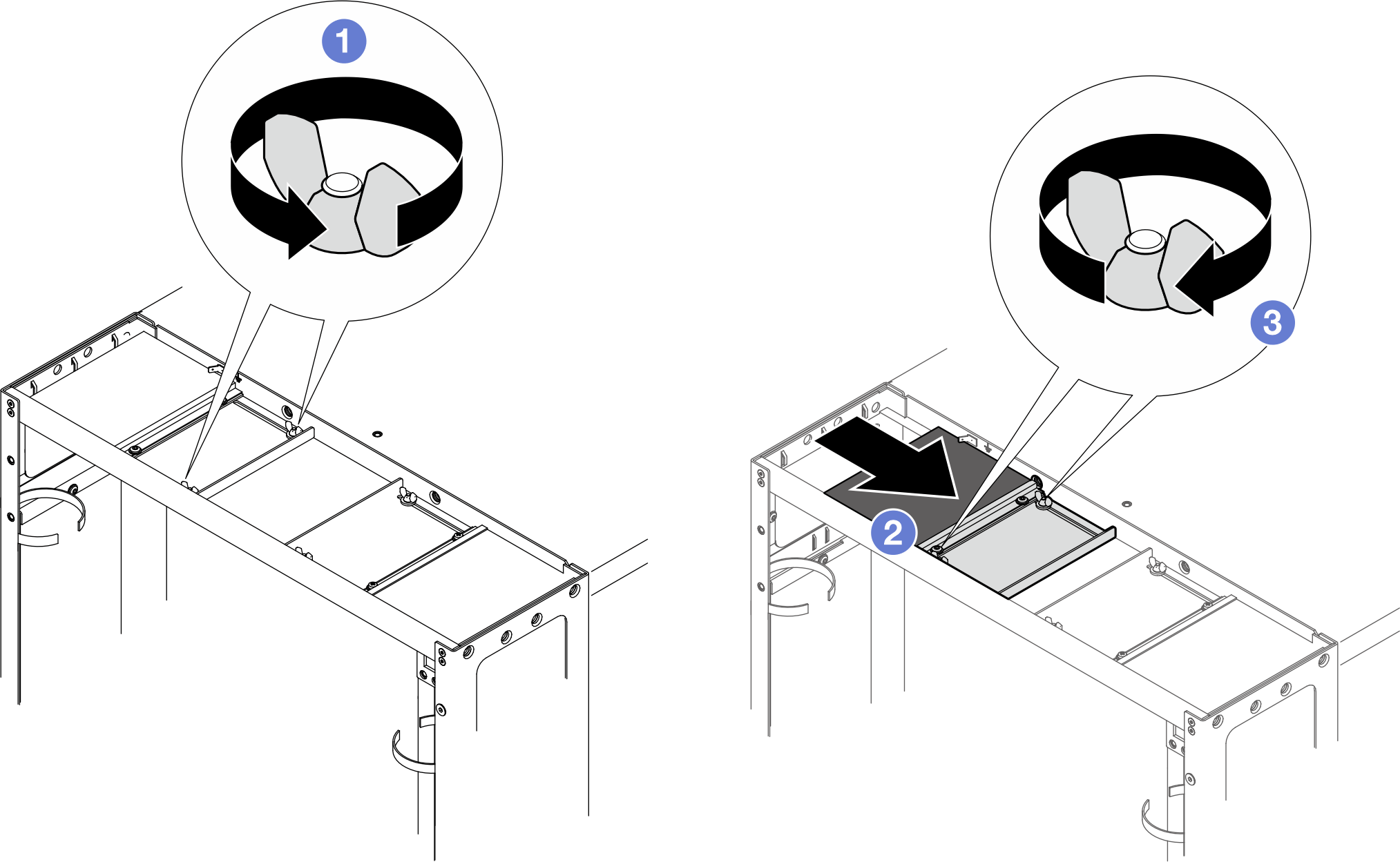
- バッフルをトップ・カバーに固定している 2 本のねじを緩めます。
- バッフルとブラシ・パネルをトップ・カバーの中央に向けてスライドさせます。
- 2 本のねじを締めてバッフルを固定します。
ブラシ・パネルの取り外し
図 22. ブラシ・パネルの取り外し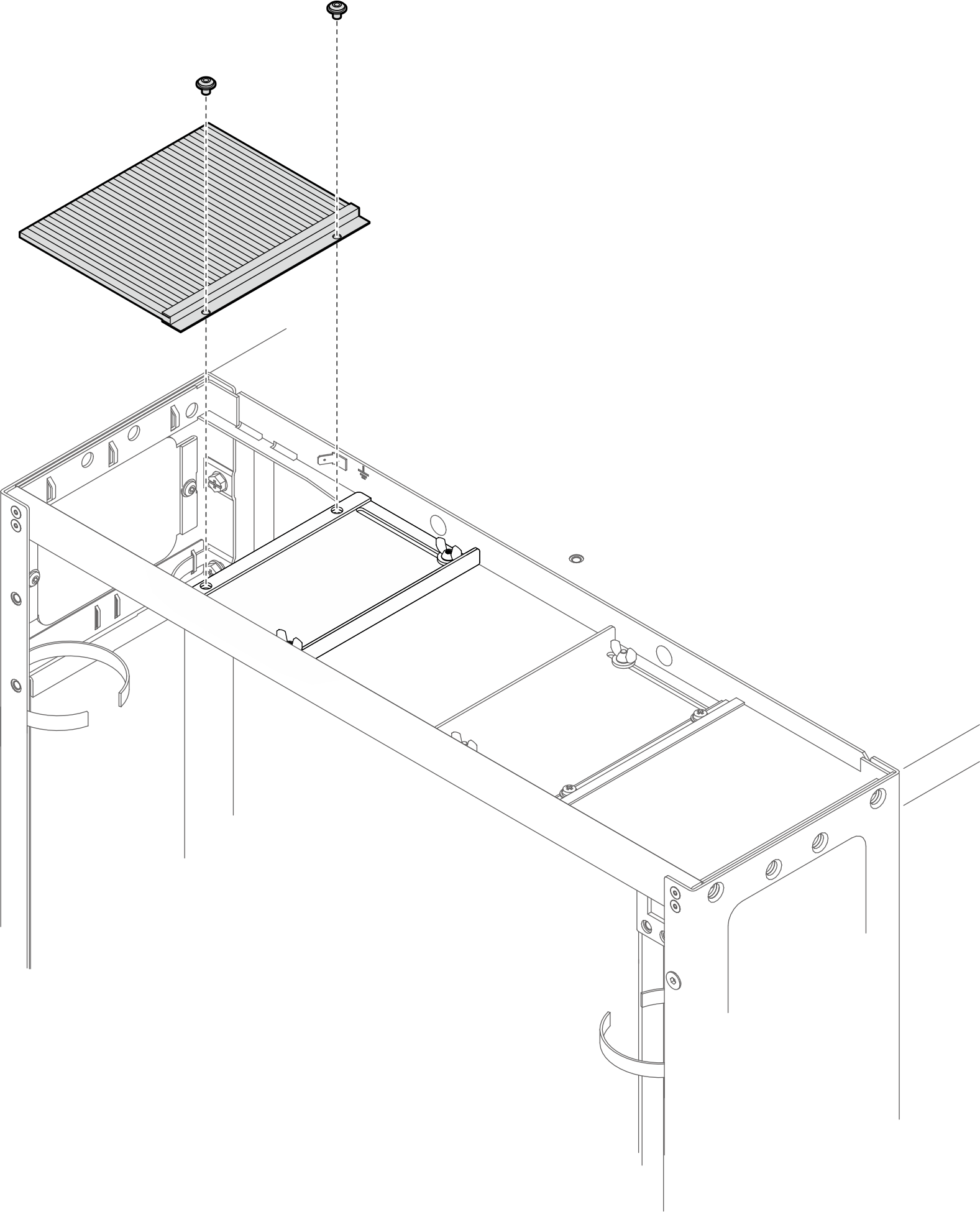
2 本のねじを緩めて、トップ・カバーからブラシ・パネルを取り外します。
ブラシ・パネルとバッフルの取り外し
図 23. ブラシ・パネルとバッフルの取り外し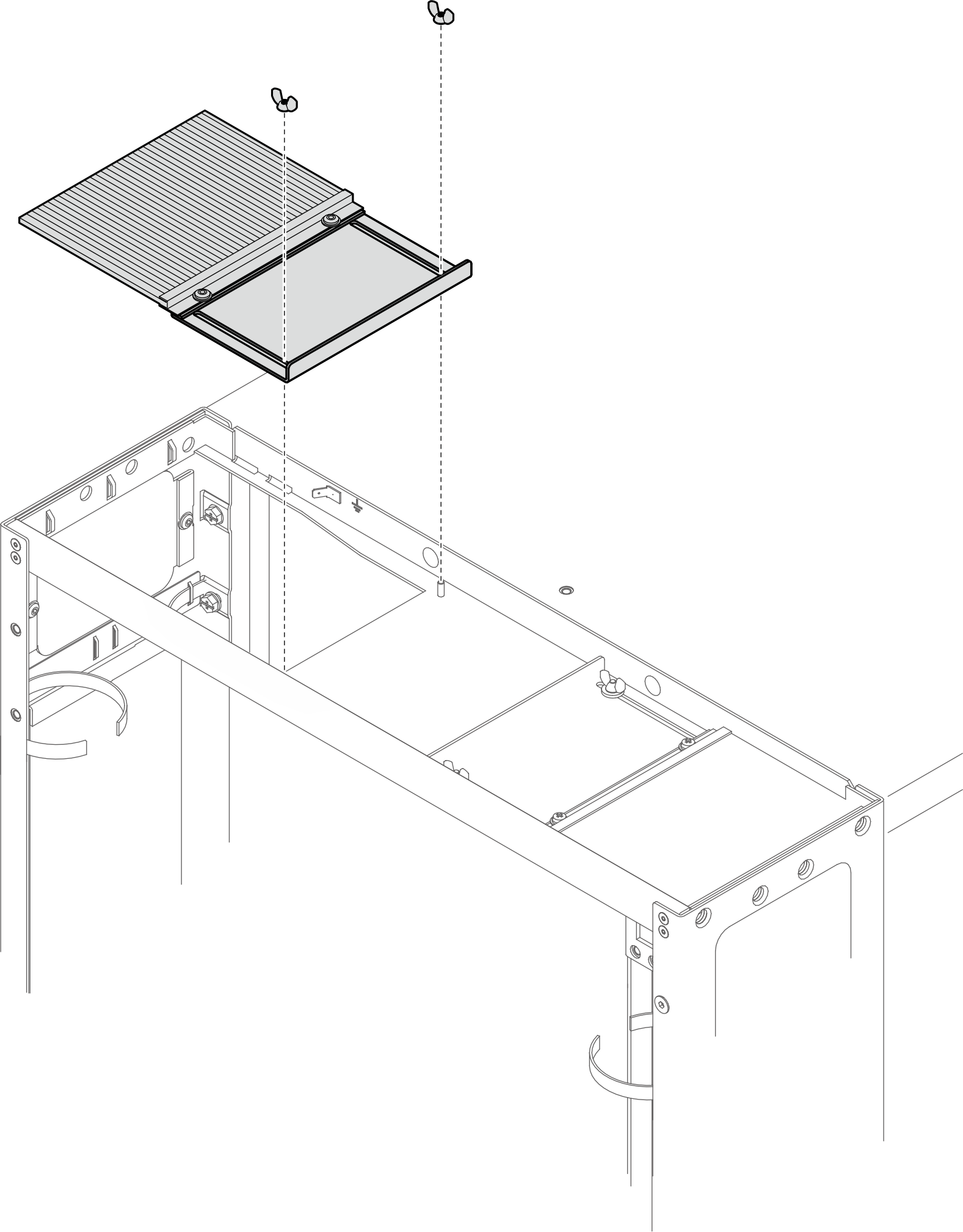
2 本のねじを緩めて、ブラシ・パネルとバッフルをトップ・カバーから取り外します。
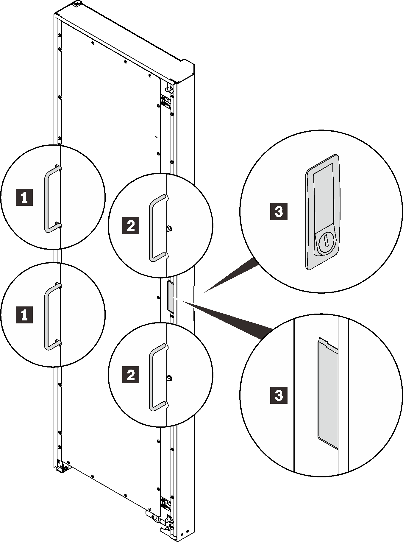
- 2 本のねじを締めて、ラッチ・プレートを左側の拡張パネルに固定します。図 24. ラッチ・プレートの取り付け

- 右側の拡張パネルから 2 つのドアストッパーを取り外します。図 25. ドアストッパーの取り外し
- 下部ヒンジを 4 本のねじで右側の拡張パネルに固定します。図 26. 下部ヒンジの固定
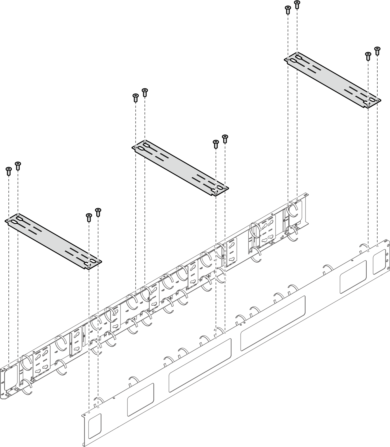
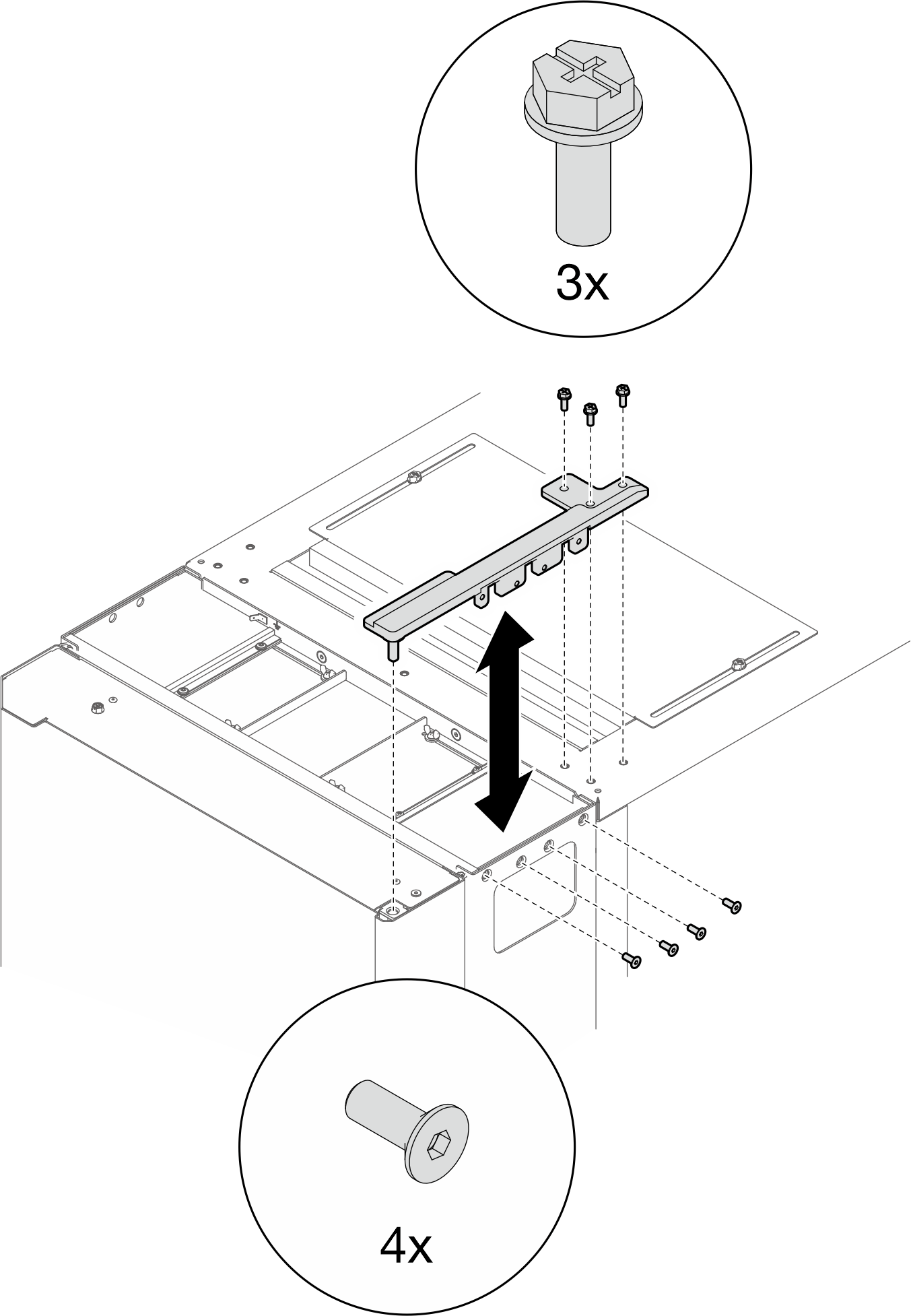
- ラックを配送する必要がある場合は、3 つのサポート・ブラケットを取り付け、ステップ 12 から 17 に進みます。注RDHX を取り付けるには、現場に到着したらサポート・ブラケットを取り外す必要があります。図 27. サポート・ブラケットの取り付け
- カートンの底面を自分に向けて、カートンの上部を取り外し、右側の 2 つのカートンの角にナイフで切れ目を入れます。次に、右側のカートン・パネルを地面に向かって折り曲げ、3 つのカートン・インサートを下向きに回転させます。図 28. 熱交換器の開梱
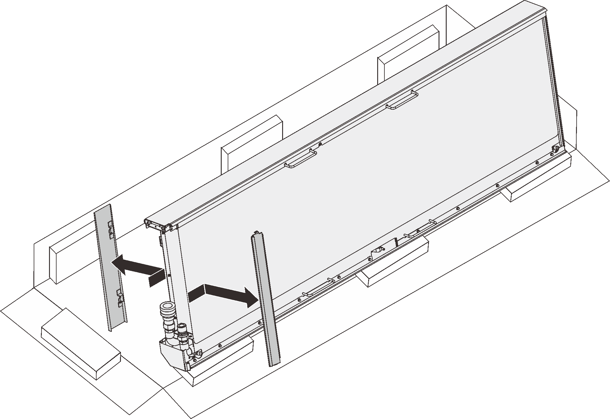
上面 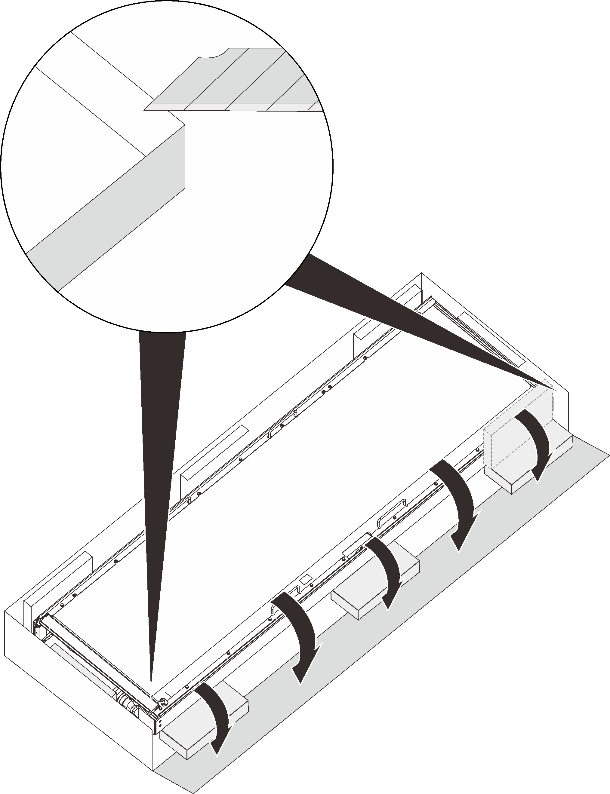
下面 - 3 人で、熱交換器を 3 つのカートン・インサート上で垂直になるように回転させます。次に、1 人が熱交換器を支えながら、内側と外側のホース・アクセス・パネルを取り外します。図 29. ホース・アクセス・パネルの取り外し
- 図のように、3 人がハンドル/スポットを持ち、熱交換器を持ちます。次に、熱交換器を慎重に持ち上げ、直立させます。図 30. 3 人での熱交換器の持ち上げ
1 1 人目が持つハンドル 3 3 人目が持つスポット 2 2 人目が持つハンドル - 3 人で熱交換器をキャビネット・フレームに運びます。下部の角を下部のヒンジ・ピンに合わせます。次に、ピンが収まるまで熱交換器を下げます。図 31. ラック・キャビネットへの熱交換器の取り付け
- 熱交換器を 2 人で所定の位置に保持します。上部のヒンジ・ピンを熱交換器に挿入します。次に、ヒンジを 7 本のねじで固定します。注このステップでは、7 本のねじを完全に締めないでください。図 32. 上部ヒンジの取り付け
フィードバックを送る