Node rear view
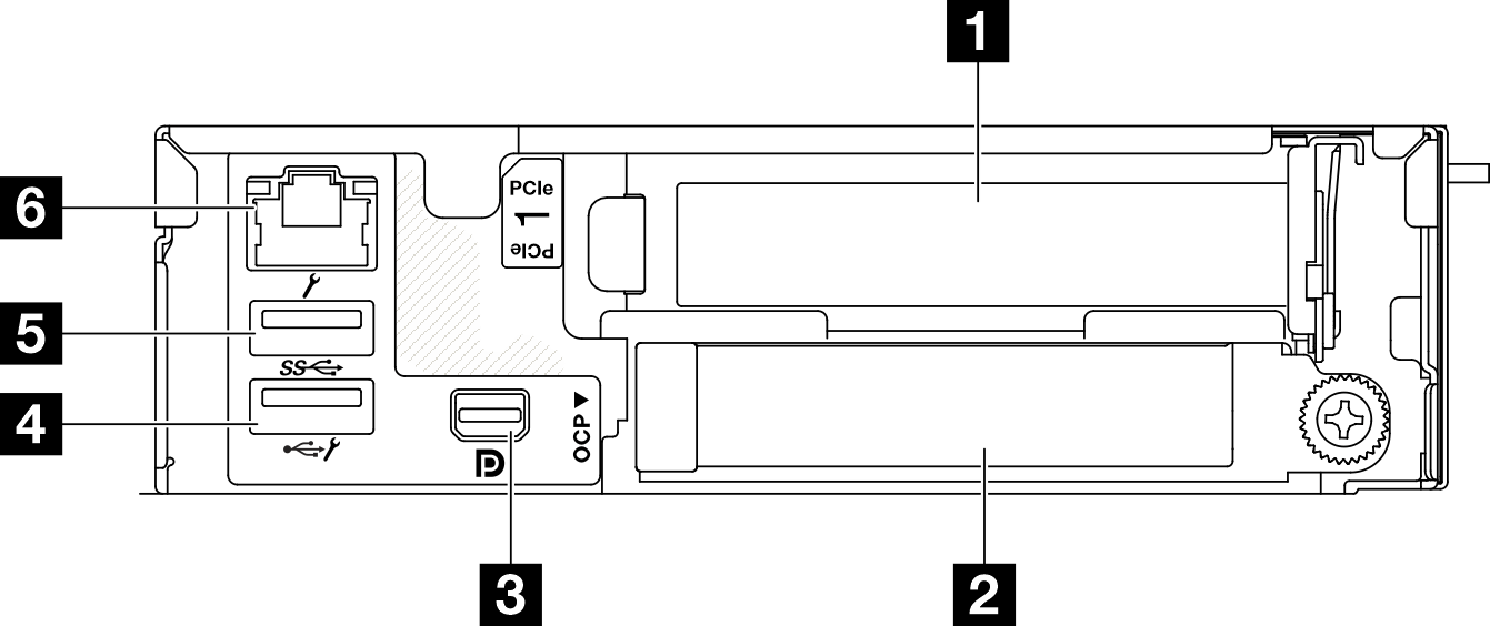
This section contains information on the controls and connectors on the rear of the ThinkSystem SD520 V4 node.
1 PCIe slot
Install PCIe adapters into these PCIe slots. See Install a PCIe adapter.
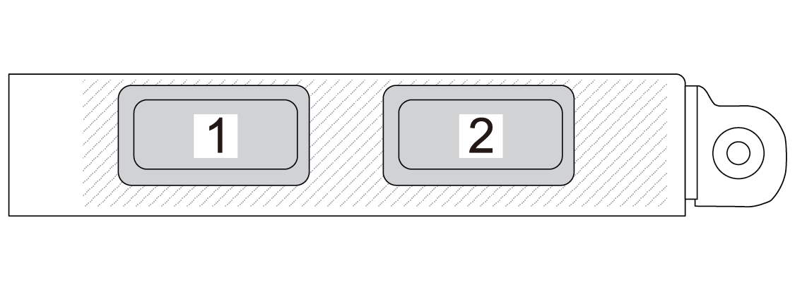
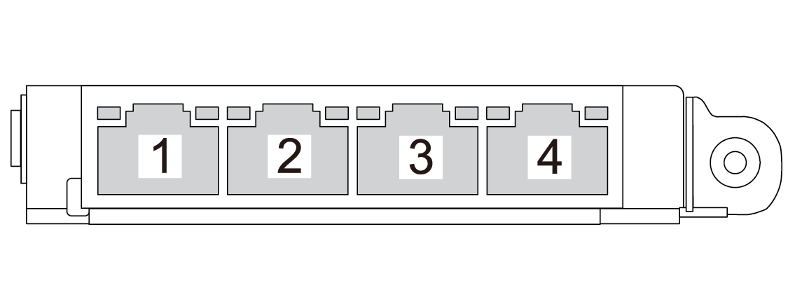
2 OCP slot


3 Mini DisplayPort connector
Connect a Mini DisplayPort-compatible video device, such as a monitor, to this connector.
4 USB 2.0 connector with Lenovo XClarity Controller (XCC) management
Connection to Lenovo XClarity Controller is primarily intended for users with a mobile device running the Lenovo XClarity Controller mobile application. When a mobile device is connected to this USB port, an Ethernet over USB connection is established between the mobile application running on the device and the Lenovo XClarity Controller.
Select Network in BMC Configuration to view or modify settings.
Four types of settings are available:
Host only mode
In this mode, the USB port is always solely connected to the server.
BMC only mode
In this mode, the USB port is always solely connected to Lenovo XClarity Controller.
Shared mode: owned by BMC
In this mode, connection to the USB port is shared by the server and Lenovo XClarity Controller, while the port is switched to Lenovo XClarity Controller.
Shared mode: owned by host
In this mode, connection to the USB port is shared by the server and Lenovo XClarity Controller, while the port is switched to the server.
5 XCC system management port (10/100/1000 Mbps RJ-45)
The node has a 10/100/1000 Mbps RJ-45 connector dedicated to Lenovo XClarity Controller, which cannot be accessed directly from the production network. A dedicated management network provides additional security by physically separating the management network traffic from the production network. You can use the Setup Utility to configure the node to use a dedicated systems-management network or a shared network.
6 USB 3.2 Gen 1 (5 Gbps) connector
Connect a USB device, such as a mouse, keyboard, or other devices, to this connector.
