Top view
This section contains information on the top view of the node.
Note
Depending on the specific configuration, the hardware might look slightly different from the illustrations in this section.
Figure 1. Top view of node
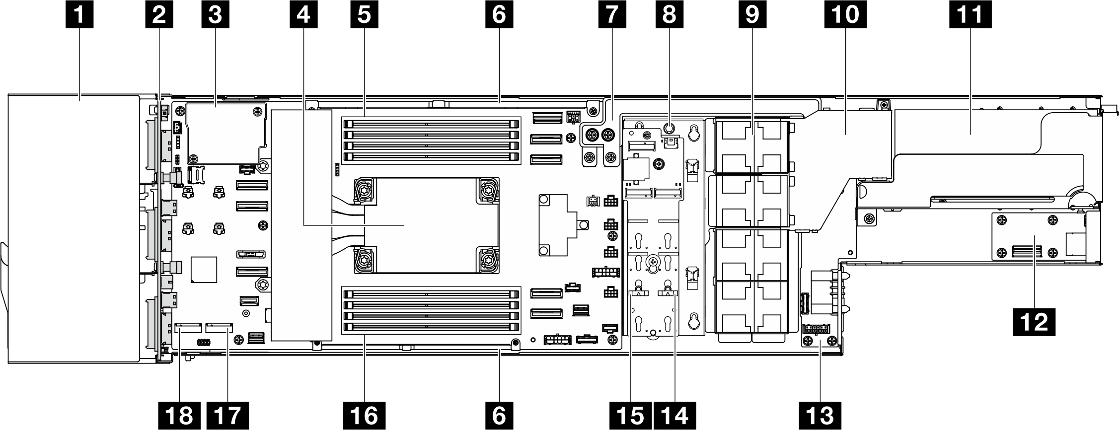
| 1 Drive cage | 2 Drive backplane or front I/O board |
| 3 Firmware and RoT security module | 4 Processor and heat sink |
| 5 Memory modules 5-8 | 6 Cable wall |
| 7 Power bus bar | 8 M.2 boot adapter or flash power module |
| 9 Fans and fan cage | 10 Air duct |
| 11 PCIe riser assembly | 12 Rear I/O module |
| 13 Power distribution board | 14 M.2 bay 1 |
| 15 M.2 bay 0 | 16 Memory modules 1-4 |
| 17 M.2 bay 2 | 18 M.2 bay 3 |
Give documentation feedback