Remove the rear I/O module
Follow instructions in this section to remove the rear I/O module.
About this task
To avoid potential danger, make sure to read and follow the safety information.
Attention
Read Installation Guidelines and Safety inspection checklist to make sure that you work safely.
Procedure
- Remove the rear I/O module.
 Remove the four screws from the rear I/O module as illustrated.
 Slightly pull the rear I/O module toward the front of the node; then, lift it out of the node.
Figure 1. Removal of the rear I/O module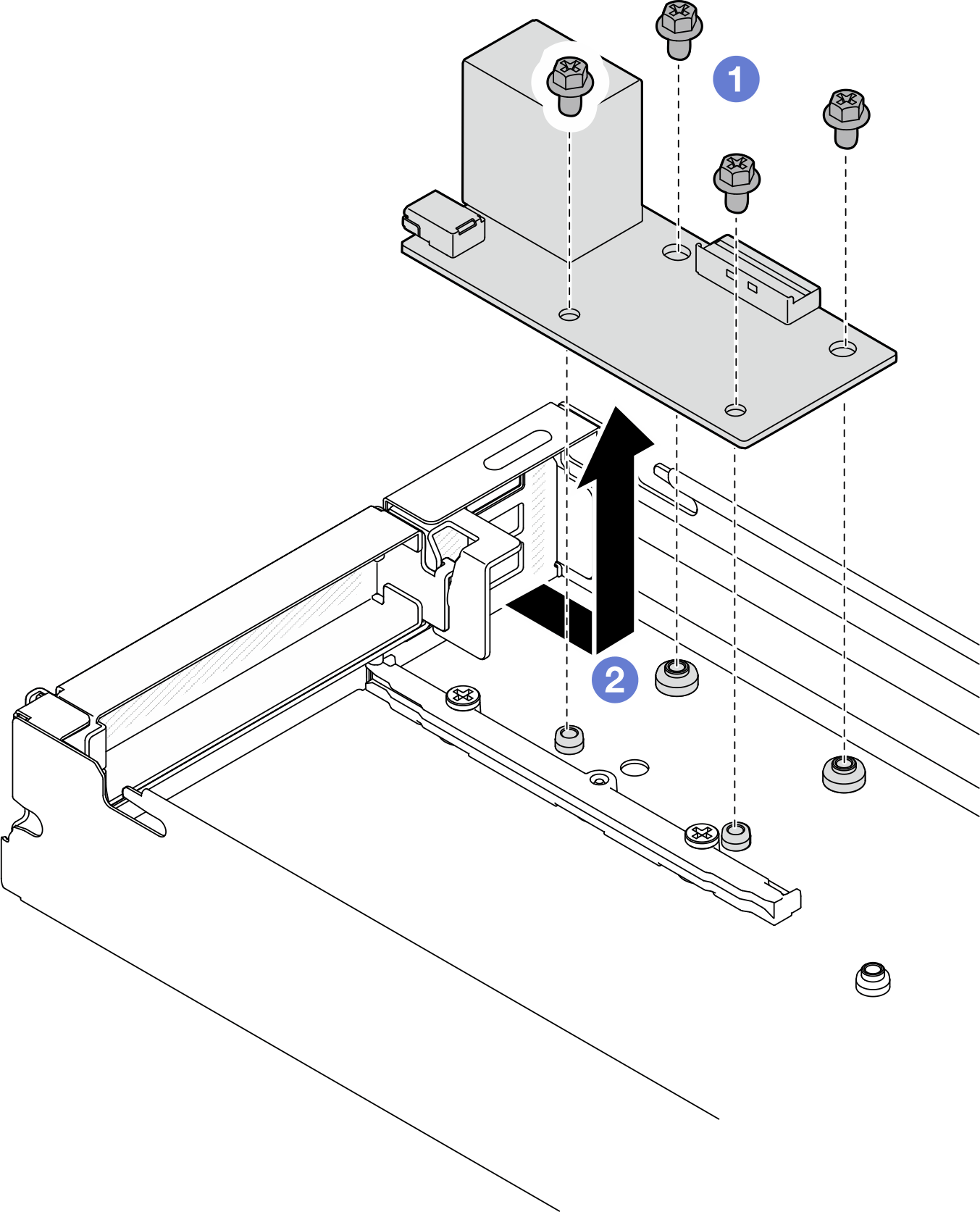
After you finish
- Install a replacement unit (see Install a rear I/O module).
- If you are instructed to return the component or optional device, follow all packaging instructions, and use any packaging materials for shipping that are supplied to you.
Demo video
Give documentation feedback