Enclosure rear overview
SMM information is displayed in this view.
Management Module
Current power supply unit
Fan
Management Module
Management Module: Indicates the status of SMM
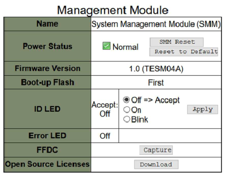
Status: Indicates the SMM operating status.
SMM Reset: After this button is clicked, SMM will start counting down 90 seconds, then show the following information.
Figure 2. Notification of successful reset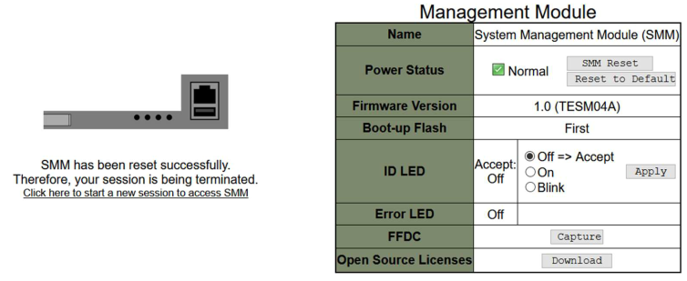
Reset to Default: Restored the SMM settings to out-of-factory default
Following are the reset settings corresponding default values:- SMTP: All email alert disabled; Email Server address = 0.0.0.0; Authentication disabled; as shown in the following figure. See SMTP/SNMP/PEF for details.
- SNMP: All traps disabled; Community Name = ”public”; as shown in the following figure. See SMTP/SNMP/PEF for details.
- PEF: None of the filter selected; Global Alerting unchecked.
Network Configuration (see Network Configuration for details):
General Settings: Host Name = ”SMM-$MAC_ADDR”; DNS Domain Name = “lenovo.com”.
Network Interface Configuration:
Auto Negotiation = on, Dynamic DNS = unchecked, Use DHCP for DNS Domain Name = unchecked, Respond to ARP = checked; IPv4 = Enabled, Use DHCP first, then static= checked, (Default static IP: IP Address = 192.168.70.100, Subnet Mask = 255.255.255.0, Gateway = 192.168.70.1), Preferred/Alternate DNS Server = blank; IPv6 = Enabled, Use DHCP to obtain DNS server addresses = unchecked, Preferred/Alternate DNS Server = blank; VLAN = disabled.
- Time Settings: The time setting will not be reset.
- User Account: Password Policy Check Enabled by default; User name= USERID, Password = PASSW0RD (The 6th character of PASSW0RD is number zero); User Privileges = admin; see User Account for details.
Account Security (see Account Security for details):
Minimum password length = 10, Force user to change password on first access = Yes, Password expiration period (in days) = 90, Password expiration warning period (in days) = 5, Minimum password change interval (in hours) = 24, Minimum password reuse cycle (0-10) = 5, Maximum number of login failures = 5, Lockout period after maximum login failures (in minutes) = 60, Web inactivity session timeout (in minutes) = 20, IP address block for 300 seconds after 10 login failures = disabled.
Web Service: HTTPS Port Number = 443. (Notice: No default HTTP port 80)
Web Certification:
Subject Information: Country Code (CC) = US, State (S) = NC, Locality (L) = RTP Organization (O) = ThinkServer, Common Name (CN) = www.lenovo.com
Issuer Information: Country Code (CC) = US, State (S) = NC, Locality (L) = RTP, Organization (O) = ThinkServer, Common Name (CN) = ww.lenovo.com
NTP: Operation Mode = Disable, Server Time Zone = UTC
Firmware version: The current firmware version
Boot-up Flash: Indicates SMM current boot up bank. In normal operation, Boot-up flash should always be First. Only when the first flash has a hardware or firmware failure, SMM will switch to 2nd flash.
Identification LED (ID LED): This blue LED serves to visually locate an enclosure in the rack with the following three options available. To activate an option, choose it from the list and click on Apply or use the corresponding commands.
Turn Off
When this option is activated, SMM ID LED would first turn off the identification LED on all the nodes in the enclosure, and enter accept mode, in which the LED behavior is determined by the node ID LEDs.
Command to turn SMM ID LED off:
ipmitool -H %smmip% -U USERID -P PASSW0RD -I lanplus raw 0x32 0x97 0x01 0x00
Table 1. SMM ID LED accept mode behavior Node identification LEDs SMM identification LED All the node ID LEDs are off. Off No node ID LED is blinking, but one or more node ID LEDs are on. On One or more node ID LEDs are blinking. Blink NoteSMM ID LED is set in accept mode by default.
See SD530 node operator panel for more information about node ID LEDs.
Turn On
When this option is activated, all the node ID LEDs will be on except the blinking ones, which will remain blinking.
Command to turn SMM ID LED on:
ipmitool -H %smmip% -U USERID -P PASSW0RD -I lanplus raw 0x32 0x97 0x01 0x01
Blink
When this option is activated, all the node ID LEDs will be blinking regardless of previous status.
Command to turn SMM ID LED blink:
ipmitool -H %smmip% -U USERID -P PASSW0RD -I lanplus raw 0x32 0x97 0x01 0x02
Error LED: Error LED is on when critical event occurs. It will be turned off after the critical event is deasserted.
FFDC: The Fast Failure Data Collection (FFDC) instantly collects information about events and conditions that might lead up to a failure. Click Capture, the file used to analyze the problem can be downloaded from the web.
Open Source Licenses: Click on Download button to download the Open Source Licenses file of Open Source packages that used in SMM
Current power supply unit
Current power supply unit: Indicates the status of power supplies
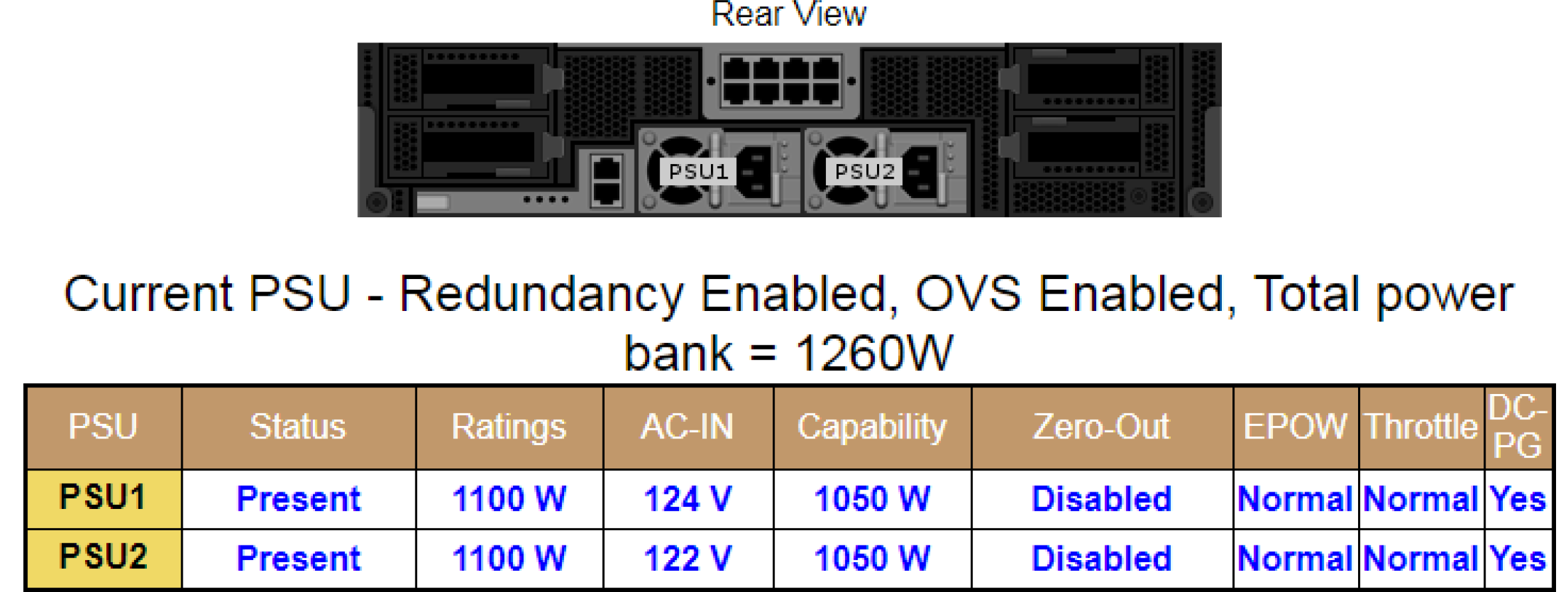
- Status
Present: The power supply is installed.
Not Present: No power supply is installed.
Fault: The power supply is in faulty condition.
Ratings: Power rating, such as 1100 W, 1600 W and 2000 W, is displayed here.
AC-IN: AC input power is displayed here.
Capability: The maximum DC output power that the power supply can provide to the entire system is displayed here.
If DC-PG of the power supply unit is No, capability will be 0 W.
If DC-PG of the power supply unit is Yes, capability usually equals the rating.
NoteThe following status are exceptions.Rating 1100 W power supply unit supports low line, capability will be 900 W (AC-IN < 100 V), 1050 W (100 V <= AC-IN < 170 V) or 1100 W (170 V <= AC-IN)
If the two power supply units of different capacities, the capability will be of the lower one.
Zero-output: Redundancy mode
Disabled: Zero-output is disabled.
Wake-Up: Zero-output is enabled. The power supply is in working state.
Sleep: Zero-output is enabled. The power supply unit is in hibernation with no DC output.
EPOW (Early power off warning)
Assert: The power supply is in AC lost condition.
Normal: The power supply AC is working.
Throttle
Assert: The power supply unit is in over-current condition.
Normal: The power supply unit is working.
DC-PG (Direct current - power good): The DC power status of the power supply.
No: The power supply is not providing the required DC power.
Yes: The power supply is providing required DC power.
Fan
Fan: Indicates the status of fans.
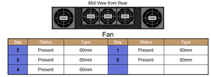
Status
Present: The fan is in normal operating condition.
Not present: No fan installed.
Fault
: The fan is in faulty condition.
- Type: There are two types of fans, 60mm and 80mm.