Node front view
This section contains information on the controls and connectors on the front of the ThinkSystem SD535 V3 node. Depending on the specific configuration, some of the components or connectors might not be supported.
Configuration with six 2.5-inch SAS/SATA/NVMe SSDs
See the following illustration for components and connectors in the configuration with six 2.5-inch SAS/SATA/NVMe SSDs.
Figure 1. Configuration with six 2.5-inch SAS/SATA/NVMe SSDs
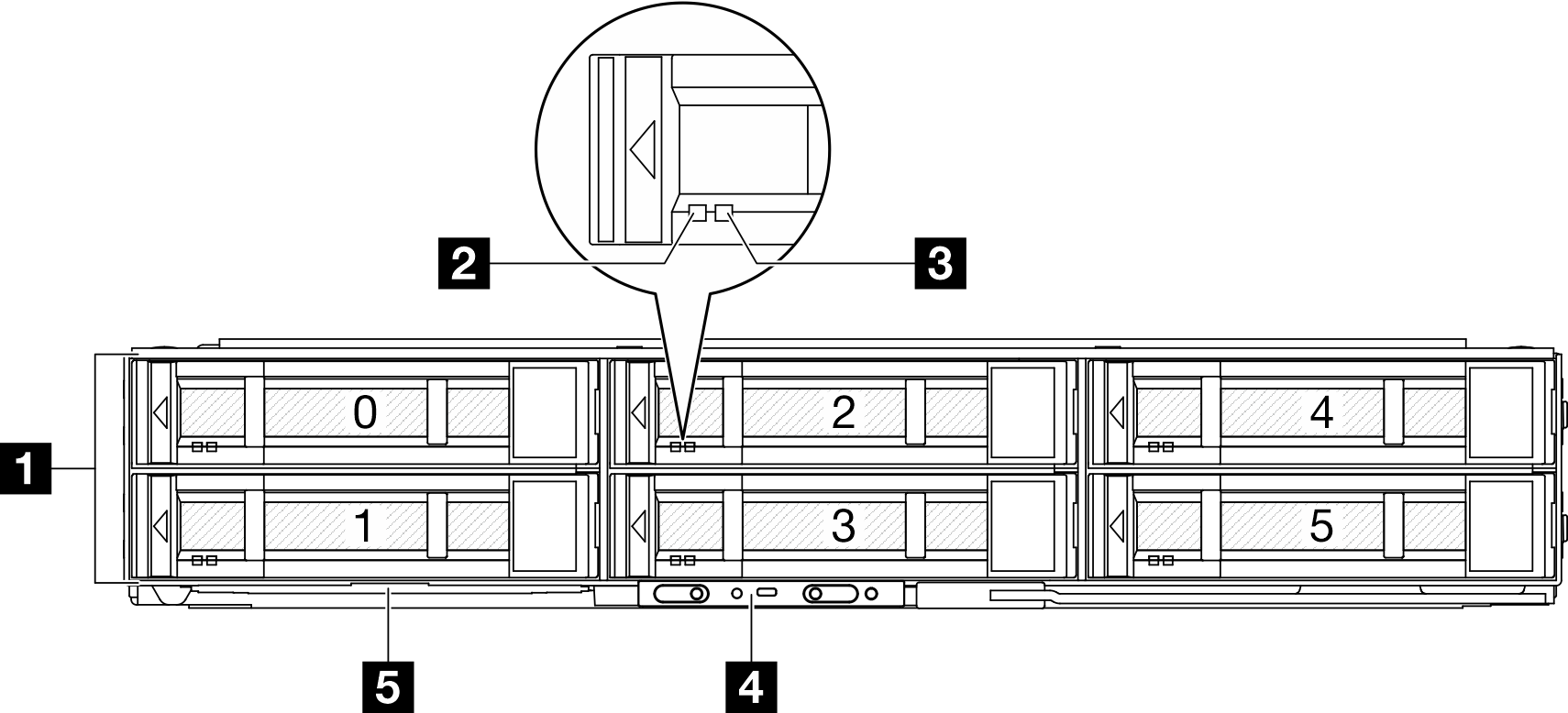
| 1 2.5-inch drive bays | 4 Front operator panel buttons and LEDs |
| 2 Drive activity LED | 5 Pull-out information tab |
| 3 Drive status LED |
1 2.5-inch drive bays
2 & 3 Drive activity LED & Drive status LED
4 Front operator panel buttons and LEDs
For more information about the front operator panel buttons and LEDs, see Front operator panel LEDs.
5 Pull-out information tab
This tab contains below information:
Network information such as MAC address and XCC network access label.
Drive bay numbers.
Give documentation feedback