Top view
This following illustration provides information on the top view of the ThinkSystem SD535 V3 node.
Note
Depending on the specific configuration, the hardware might look slightly different from the illustrations in this section.
Figure 1. Top view of SD535 V3
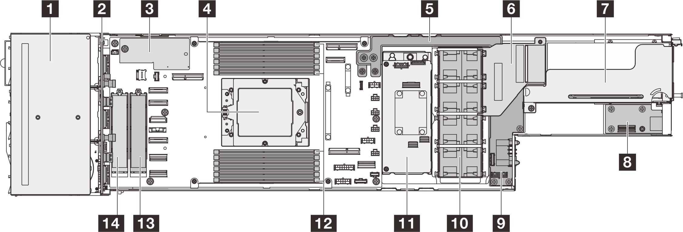
| 1 Drive cage | 8 Rear I/O module* |
| 2 2.5-inch drive backplane | 9 Power distribution board |
| 3 Firmware and RoT security module | 10 Fans and fan cage |
| 4 Processor | 11 Internal RAID adapter (CFF RAID adapter or M.2 boot adapter)* |
| 5 Power bus bar | 12 DIMMs 1-12 |
| 6 GPU air duct (required when system is installed with GPU)* | 13 M.2 bay 2 |
| 7 PCIe riser assembly* | 14 M.2 bay 3 |
Figure 2. Top view of SD535 V3 with water loop
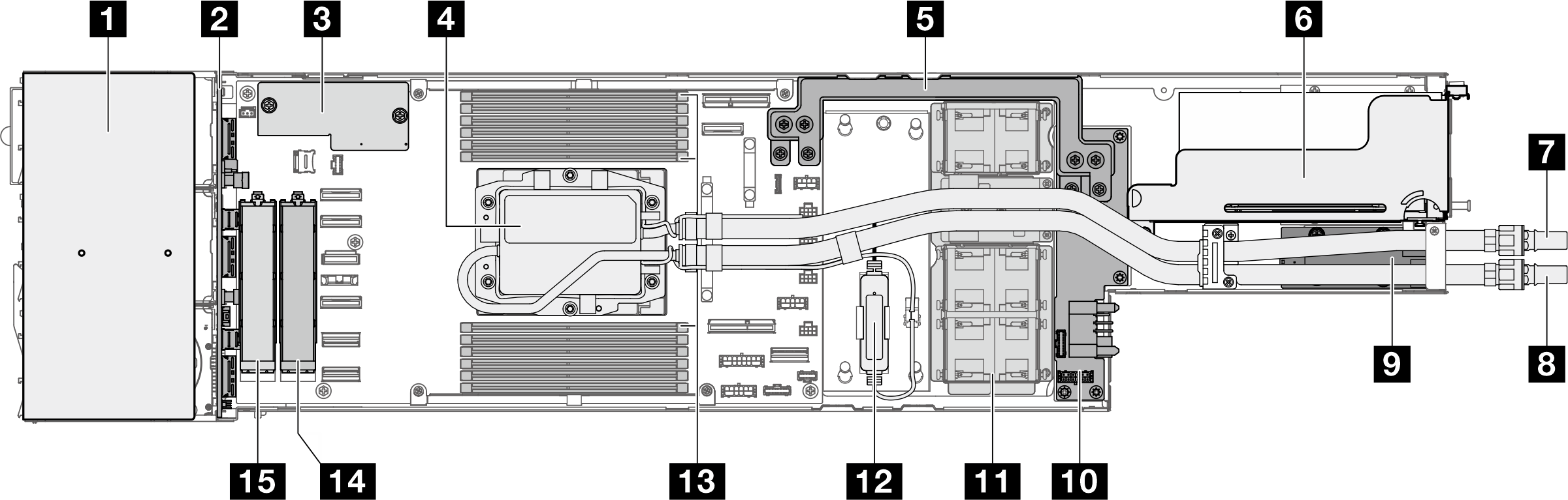
| 1 Drive cage | 9 Rear I/O module* |
| 2 2.5-inch drive backplane | 10 Power distribution board |
| 3 Firmware and RoT security module | 11 Fans and fan cage |
| 4 Processor | 12 Leakage sensor module |
| 5 Power bus bar | 13 DIMMs 1-12 |
| 6 PCIe riser assembly* | 14 M.2 bay 2 |
| 7 Outlet hose | 15 M.2 bay 3 |
| 8 Inlet hose |
Note
* Depending on the specific configuration, the node might not come with this component.
Give documentation feedback