Install a drive
Use this information to install a drive.
About this task
Read Installation Guidelines and Safety inspection checklist to ensure that you work safely.
Ensure you have SD650 V3 Neptune DWC Waterloop Service Kit
in hand to install components.
- A video of this procedure is available at YouTube.
Procedure
- For installing one 7 mm or 15 mm drive only, complete the following steps.
 Find the cable with its plugger marked as SSD 0/2, and connect it to the drive.
 Flip the drive over.
 Install the drive into the bottom of the drive cage and make sure it is secured in place.
Figure 1. 7 mm drive installation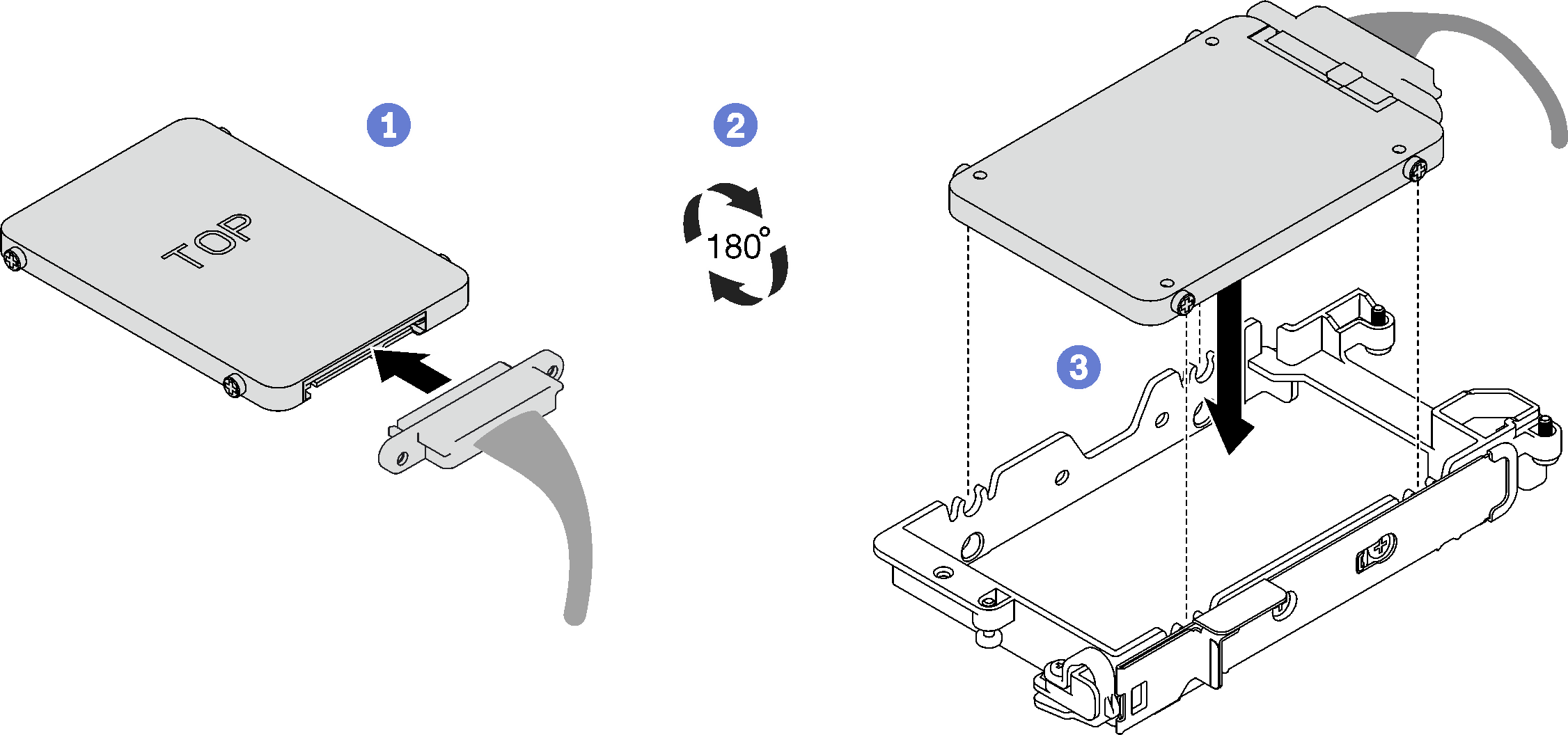 Figure 2. 15 mm drive installation
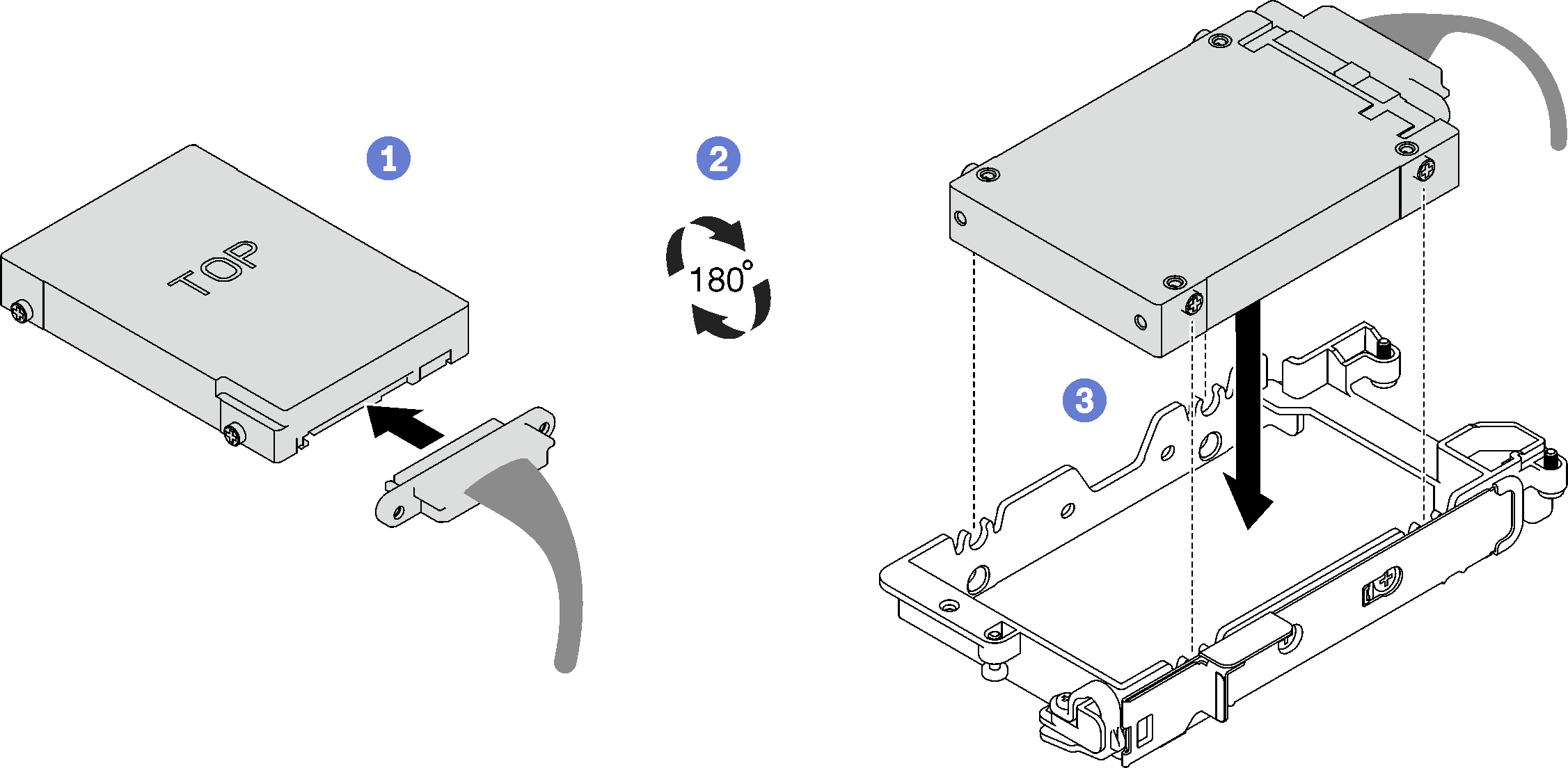 NoteSecure the unconnected cable plugger on top side of the drive cage.
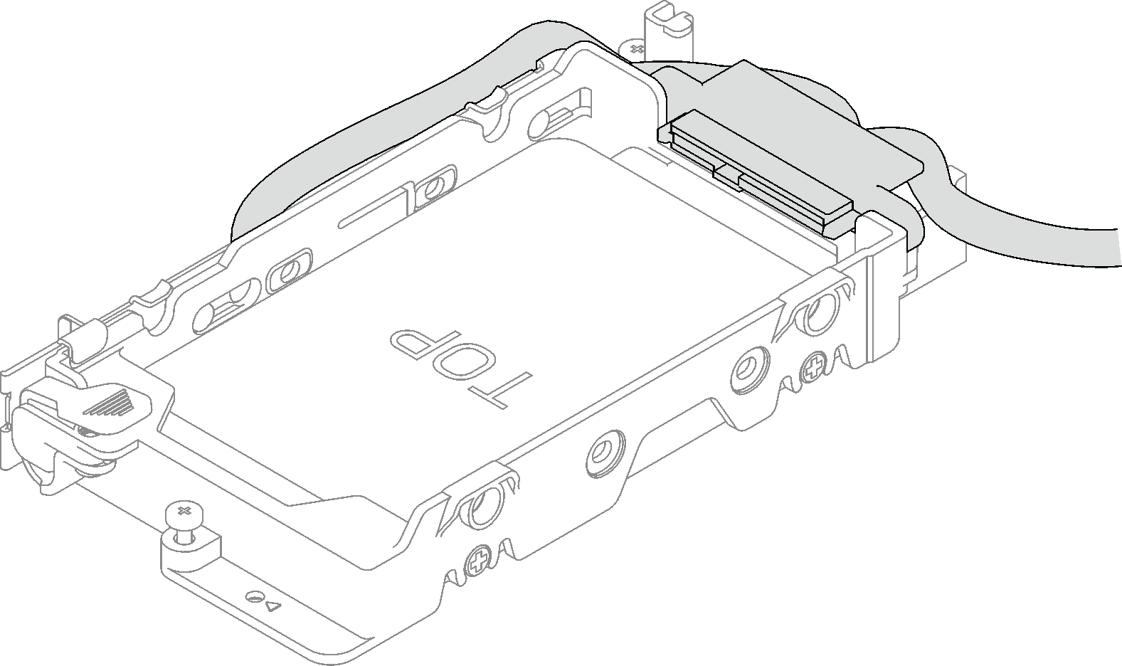
- For installing two 7 mm drives, complete the following steps.
If removed, install the conduction plate into the bottom of the drive cage and secure it with four screws.
If the gap pad located on the reverse side of the drive is damaged or detached, replace it with a new one. Make sure to follow Gap pad/putty pad replacement guidelines.
NoteMake sure the metal tab is in the unlocked position.Figure 3. Conduction plate installation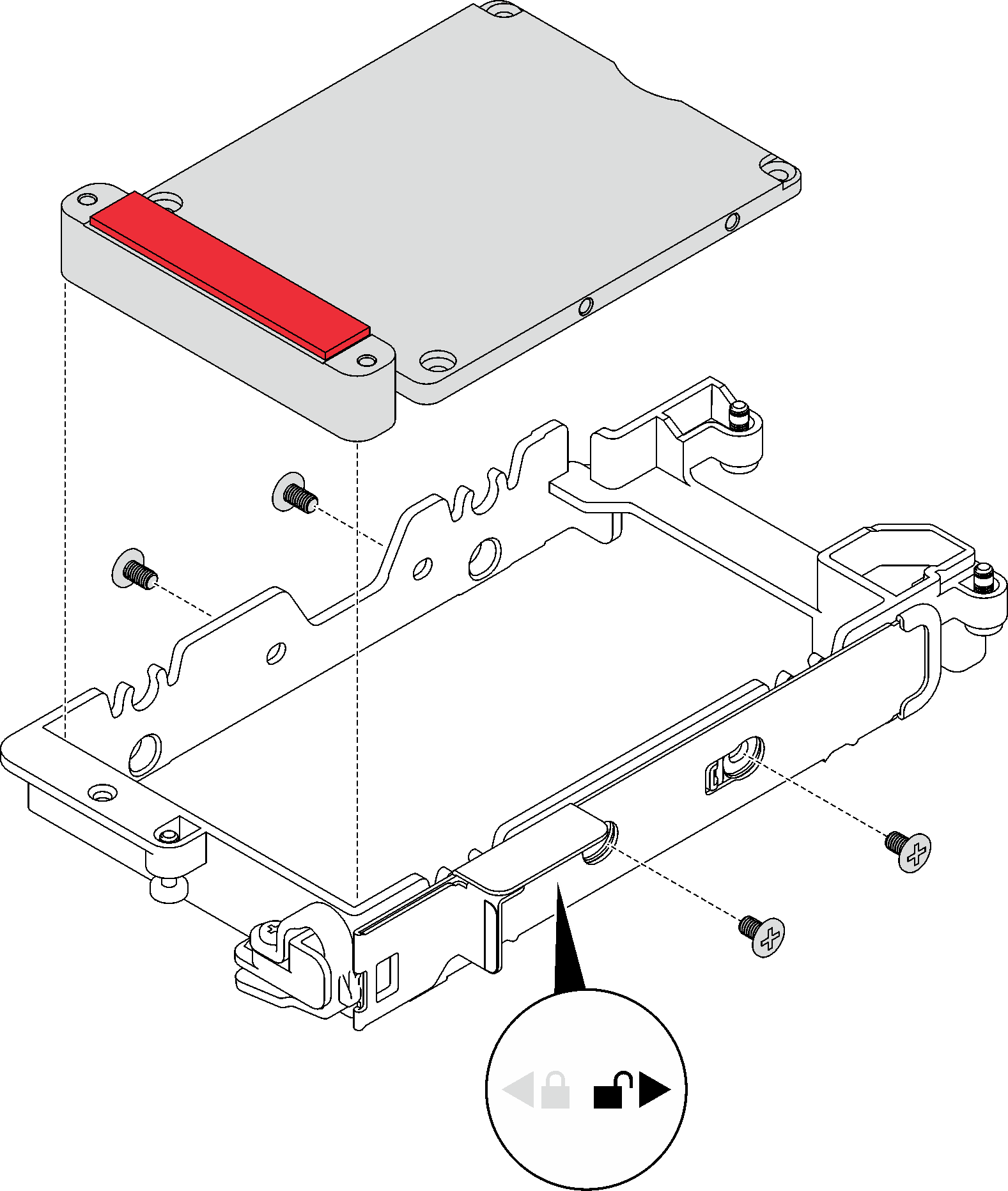
- Install the lower drive.
- Find the cable with its plugger marked as SSD 0/2, and connect it to the drive.
- Flip the drive over.
- Install the drive into the bottom of the drive cage and make sure it is secured in place.
Figure 4. Lower drive installation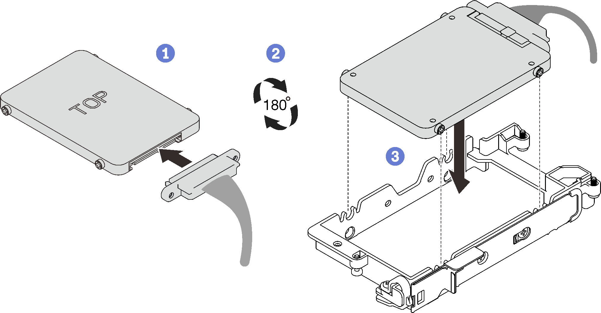
- Install the upper drive.
- Find the cable with its plugger marked as SSD 1/3, and connect it to the drive. Then, pivot the drive into the top of the drive cage as shown.
- Push and hold the release latch.
- Slide the metal tab to the locked position.
Figure 5. Upper drive installation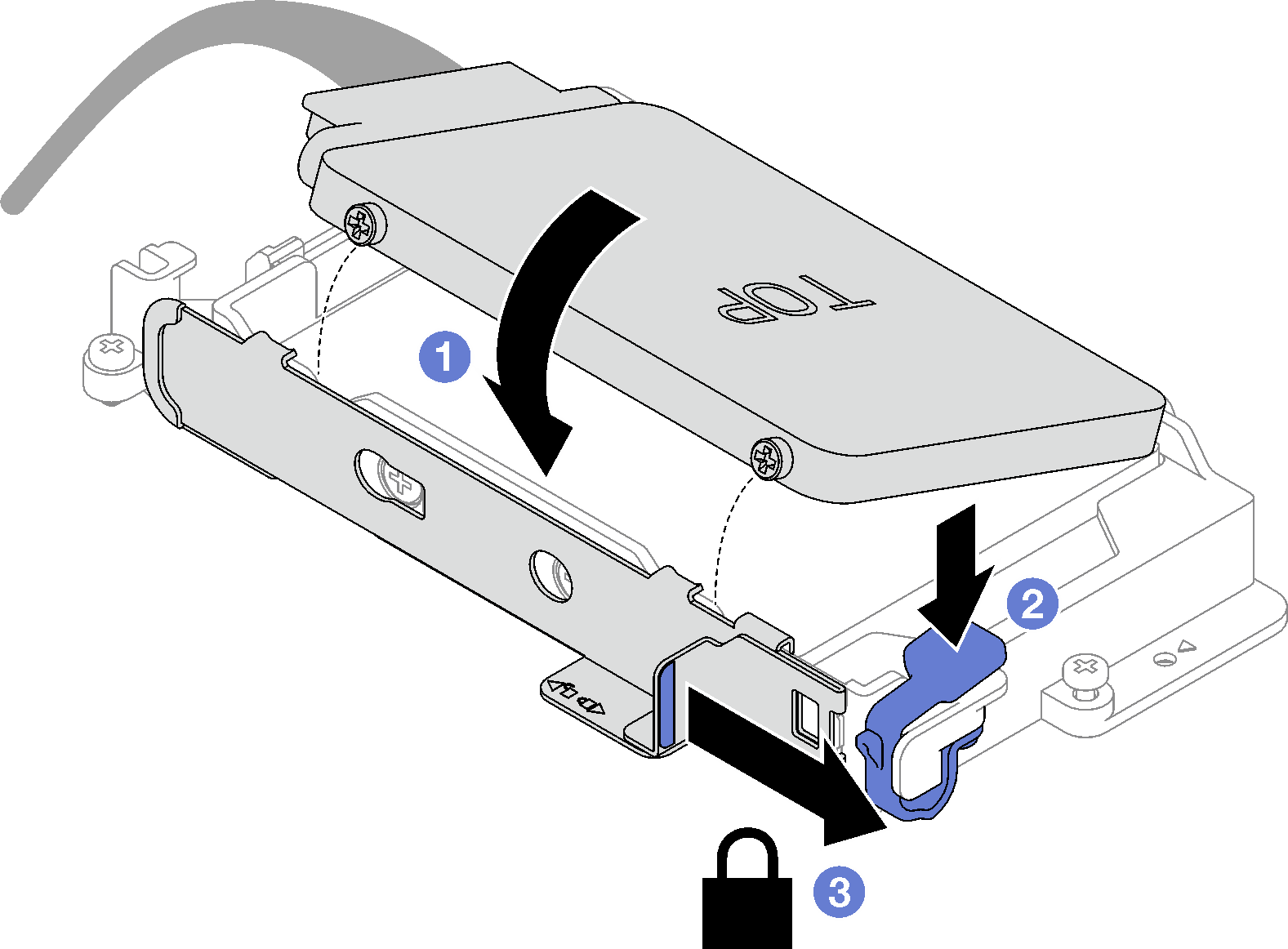
Install the drive cage. See Install a drive cage assembly.
Install the cross braces. See Install the cross braces (SD650 V3).
Install the tray cover. See Install the tray cover.
Install the tray into the enclosure. See Install a DWC tray in the enclosure.
- Connect all required external cables to the solution.NoteUse extra force to connect QSFP cables to the solution.
Check the power LED on each node to make sure it changes from fast blink to slow blink to indicate all nodes are ready to be powered on.