Instructions concernant la configuration de plateaux mixtes pour le boîtier DW612S
Reportez-vous à la section suivante pour en savoir plus sur l’installation de différents plateaux de refroidissement direct par eau dans le boîtier du DW612S.
Plateaux DWC pris en charge par le boîtier DW612S
SD650 V2
SD650-N V2
SD650 V3
SD650-I V3
SD650-N V3
SD665 V3
SD665-N V3
Instructions concernant les plateaux mixtes
Le boîtier DW612S permet la configuration de plateaux mixtes, c’est-à-dire l’installation de différents plateaux de support dans le même boîtier DW612S. La configuration des plateaux mixtes doit répondre aux exigences suivantes.
La consommation d’énergie totale du boîtier est passée en revue et approuvée dans Site Web de Lenovo Capacity Planner.
SMM2 est mis à jour vers la version la plus récente du microprogramme.
Si SD665-N V3 ou SD650-N V3 est installé dans le boîtier, seuls les PSU de 2 600 ou 7 200 watts sont pris en charge.
Si SD650 V2 ou SD650 V3 est installé dans le boîtier et si la configuration des E-S partagées est activée, la séquence de mise sous tension et hors tension du nœud spécial d’E-S partagées doit être respectée. Consultez Séquence de mise sous tension et hors tension spécifique à la configuration des E-S partagées.
Installez le plateau en commençant par le bas du boîtier et en allant vers le haut (du nœud 1-2 au nœud 11-12). L’ordre d’installation des plateaux dans le boîtier doit être le suivant :
Figure 1. Vue avant du boîtier DW612S installé avec six plateaux SD650 V3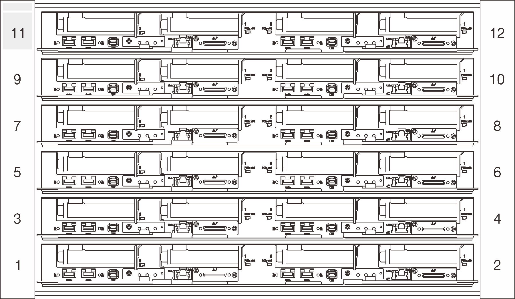
Consultez Site Web Lenovo Press pour connaître la température d’eau d’entrée maximale prise en charge par le plateau et le débit de flux minimal requis. Réglez le point de consigne de la température du CDU de manière à ce que l’eau d’entrée la plus basse possible ne soit pas dépassée. Réglez le point de consigne du débit du CDU pour vous assurer que le débit minimum le plus élevé est délivré à chaque plateau.
Si vous rencontrez une erreur système lors de la configuration des plateaux mixtes, vérifiez si le système satisfait aux exigences ci-dessus. Si l’erreur système persiste, contactez un technicien Lenovo.
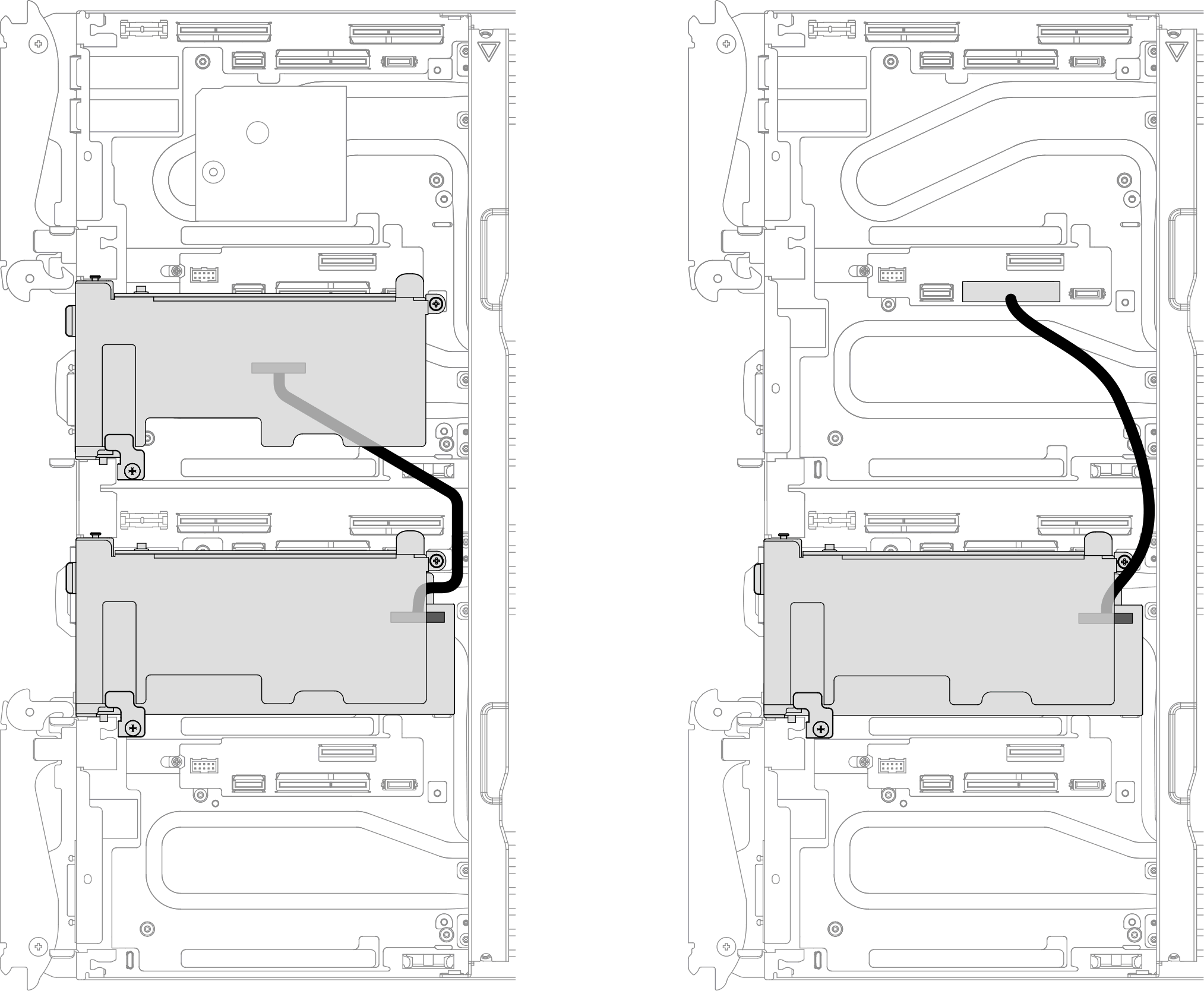
Vu de l’avant du plateau, le nœud de droite est installé avec l’adaptateur principal, tandis que le nœud de gauche est soit installé avec le kit d’adaptateur auxiliaire, soit connecté à l’adaptateur principal avec le câble des E-S partagées.
Séquence de mise sous tension : mettez d’abord sous tension le nœud de droite, puis le nœud de gauche.
Séquence de mise hors tension : mettez d’abord hors tension le nœud de gauche, puis le nœud de droite.