System board connectors
Use this information to locate compute node system board components and connectors for optional devices.
The following illustration shows the system board components, including connectors for users to install optional devices in the compute node.
Figure 1. System-board connectors
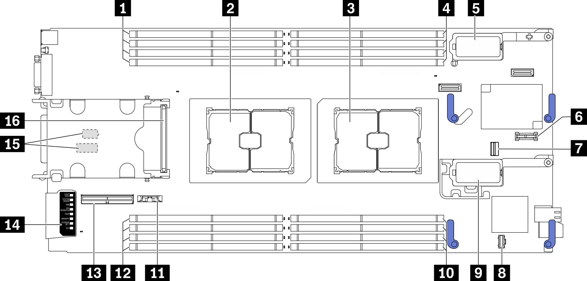
| 1 Memory module slots 9–12 | 9 I/O expansion adapter 2 connector Note Ethernet I/O expansion adapter and fiber channel I/O expansion adapter. |
| 2 Processor socket 2 | 10 Memory module slots 5–8 |
| 3 Processor socket 1 | 11 CMOS battery - CR2032 |
| 4 Memory module slots 1–4 | 12 Memory module slots 13–16 |
| 5 I/O expansion adapter 1 connector. Note Ethernet I/O expansion adapter only. | 13 EDSFF backplane cable connector |
| 6 Trusted Platform Module (TPM) connector | 14 Light Path Diagnostics panel |
| 7 M.2 signal socket | 15 Switch blocks Note The switch blocks are located on the bottom side of the compute node. |
| 8 M.2 power socket | 16 Hot-swap drive backplane connector |
Give documentation feedback