System-board switches
Use this information to locate the system-board switches.
Important
- Before you change any switch settings or move any jumpers, turn off the compute node; then, disconnect all power cords and external cables. Review the following information:
- Any system-board switch or jumper block that is not shown in the illustrations in this document are reserved.
Attention
The switch blocks are located on the bottom side of the compute node. Remove the compute node from the chassis and carefully place it at the up-side-down orientation to access the switch blocks. To remove the compute node, see Remove the compute node from chassis.
The following illustration shows the location of the switch blocks on the bottom side of the compute node.
Figure 1. System-board switches
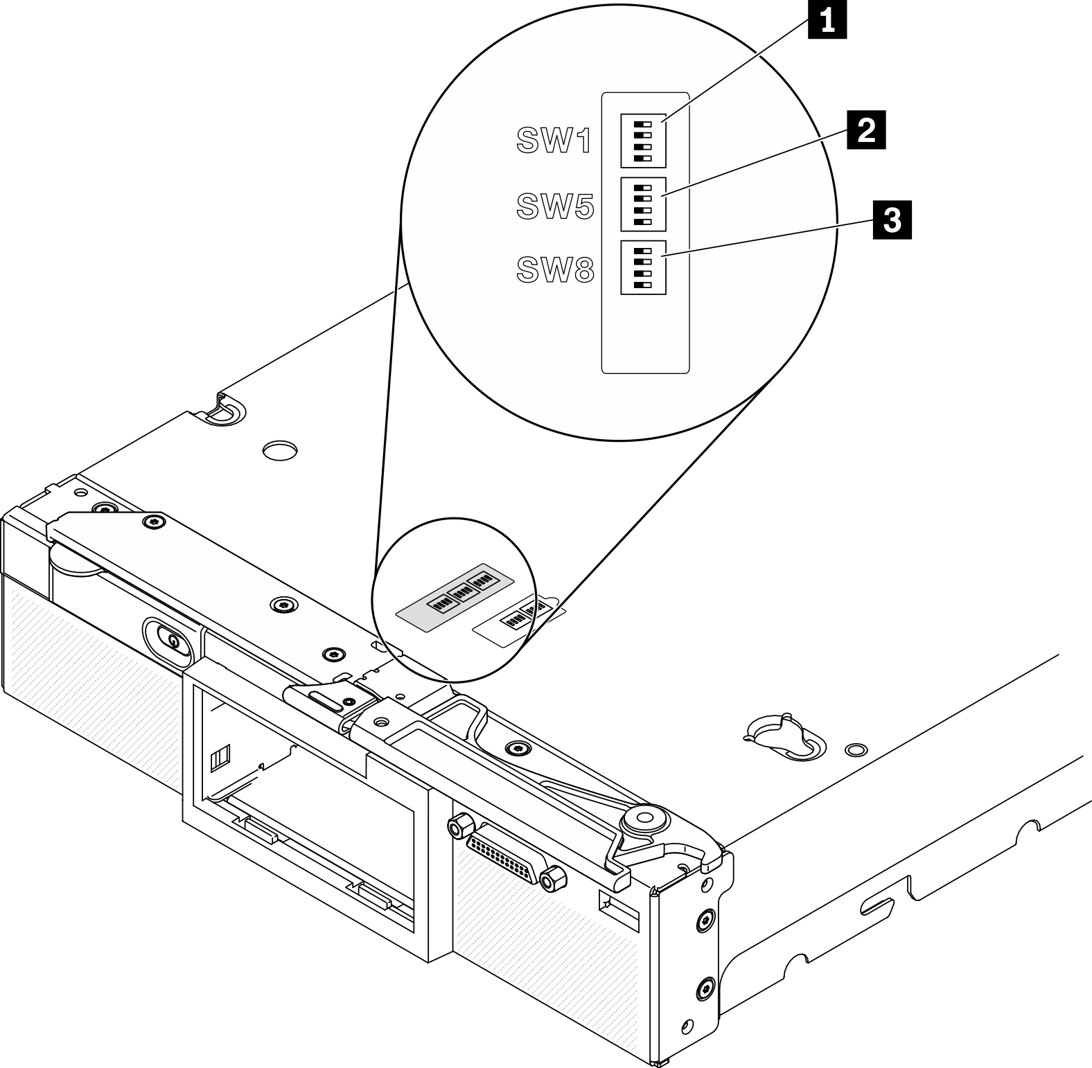
| 1 SW 1 switch block |
| 2 SW 5 switch block |
| 3 SW 8 switch block |
Switch and jumper functions are as follows:
- All jumpers on the system board are reserved and should be removed.
The following table describes the functions of the switches on switch block SW1.
Table 2. System-board switch block SW1 Switch number Description Definition SW1–1 ME recovery The default position is Off. Changing the switch to the On position to enable ME boots to recovery SW1–2 ME firmware security override The default position is Off. For debug only. SW1–3 Power permission The default position is Off. Changing this switch to the On position enables Power On SW1-4 BMC reset The default position is Off. Changing this switch to the On position forces the compute node to reset the BMC. The following table describes the functions of the switches on switch block SW5.
Table 3. System-board switch block SW5 Switch number Description Definition SW5-1 Password override The default position is Off. Changing this switch to the On position overrides the power-on password. SW5-2 Reserved and should be kept in the off position. SW5-3 Real time clock (RTC) reset The default position is Off. Changing this switch to the On position resets the RTC. A momentary toggle is all that is required. To avoid excessive CMOS battery drain, do not leave this switch in the On position. SW5-4 Serial select The default position is Off (send the serial input output (SIO) to the front serial port). Changing this switch to the On position sends the BMC to the serial port. The following table describes the functions of the switches on switch block SW8.
Table 4. System-board switch block SW8 Switch number Description Definition SW8-1 Boot backup XClarity Controller When the switch is in the default Off position, the compute node will boot by using the primary XClarity Controller firmware. When the switch is in the On position, the compute node will boot by using a backup of the XClarity Controller firmware. SW8-2 Reserved and should be kept in the off position. SW8-3 iBMC force update The default position is Off. Changing this switch to the On position bypasses the operational firmware image and performs a BMC firmware update, if the normal firmware update procedure results in an inoperative BMC. NoteUse this switch only if the normal firmware update procedure fails and the operational firmware image is corrupted. Use of this switch disables normal baseboard management controller operation.SW8-4 Reserved and should be kept in the off position.
Give documentation feedback