Front operator panel
The front operator information panel of the server provides controls, connectors, and LEDs. The front operator panel varies by model.
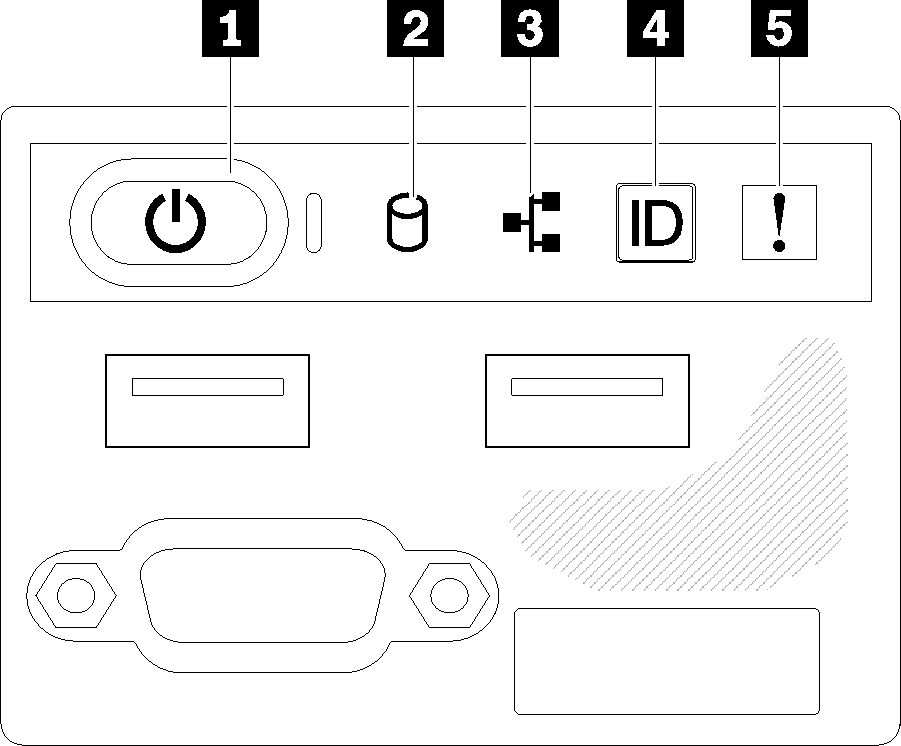
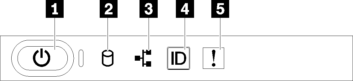
| 1 Power button and power LED (green) | 4 System ID button/LED (blue) |
| 2 Drive activity LED (green) | 5 System-error LED (yellow) |
| 3 Network activity LED (green) |
- Off: Power is not present or the power supply, or the LED itself has failed.
- Flashing rapidly (4 times per second): The server is turned off and is not ready to be turned on. The power button is disabled. This will last approximately 5 to 10 seconds.
- Flashing slowly (once per second): The server is turned off and is ready to be turned on. You can press the power button to turn on the server.
- On: The server is turned on.
2 Drive activity LED (green): Each hot-swap drive comes with an activity LED. If the LED is lit, it indicates that the drive is powered, but not actively reading or writing data. If the LED is flashing, the drive is being accessed.
3 Network activity LED (green): When this LED flickers, it indicates that the server is transmitting to or receiving signals from the Ethernet LAN.
4 System ID button/LED (blue): Use this blue LED to visually locate the server among other servers. This LED is also used as a presence detection button. You can use Lenovo XClarity Administrator to light this LED remotely.
5 System-error LED (yellow): When this yellow LED is lit, it indicates that a system error has occurred.