Memory module installation rules
Memory modules must be installed in a specific order based on the memory configuration that you implement on your server.
For Intel Xeon SP Gen 1:
Minimum: 8 GB (only one processor installed and only one 8 GB RDIMM installed in the CPU1 DIMM3 slot)
Maximum:
384 GB using RDIMMs (two processors installed and one 32 GB RDIMM installed in each of the 12 memory module slots)
768 GB using LRDIMMs (two processors installed and one 64 GB LRDIMM installed in each of the 12 memory module slots)
Type:
TruDDR4 2666, single-rank or dual-rank, 8 GB/16 GB/32 GB RDIMMs with Error Checking and Correcting (ECC) technology
TruDDR4 2666, quad-rank, 64 GB LRDIMMs with ECC technology
For Intel Xeon SP Gen 2:
Minimum: 8 GB (only one processor installed and only one 8 GB RDIMM installed in the CPU1 DIMM3 slot)
Maximum: 768 GB (two processors installed and one 64 GB RDIMM installed in each of the 12 memory module slots)
Type:
TruDDR4 2666, single-rank or dual-rank, 16 GB/32 GB RDIMMs with ECC technology
TruDDR4 2933, single-rank or dual-rank, 8 GB/16 GB/32 GB/64 GB RDIMMs with ECC technology
TruDDR4 RDIMM with ECC technology
TruDDR4 LRDIMM with ECC technology
Independent mode
Independent mode provides high performance memory capability. You can populate all channels with no matching requirements. Individual channels can run at different memory module timings, but all channels must run at the same interface frequency.
| Total memory modules | Processor 1 | Total memory modules | |||||
|---|---|---|---|---|---|---|---|
| 6 | 5 | 4 | 3 | 2 | 1 | ||
| 1 | 3 | 1 | |||||
| 2 | 4 | 3 | 2 | ||||
| 3 | 4 | 3 | 2 | 3 | |||
| 4 | 5 | 4 | 3 | 2 | 4 | ||
| 5 | 5 | 4 | 3 | 2 | 1 | 5 | |
| 6 | 6 | 5 | 4 | 3 | 2 | 1 | 6 |
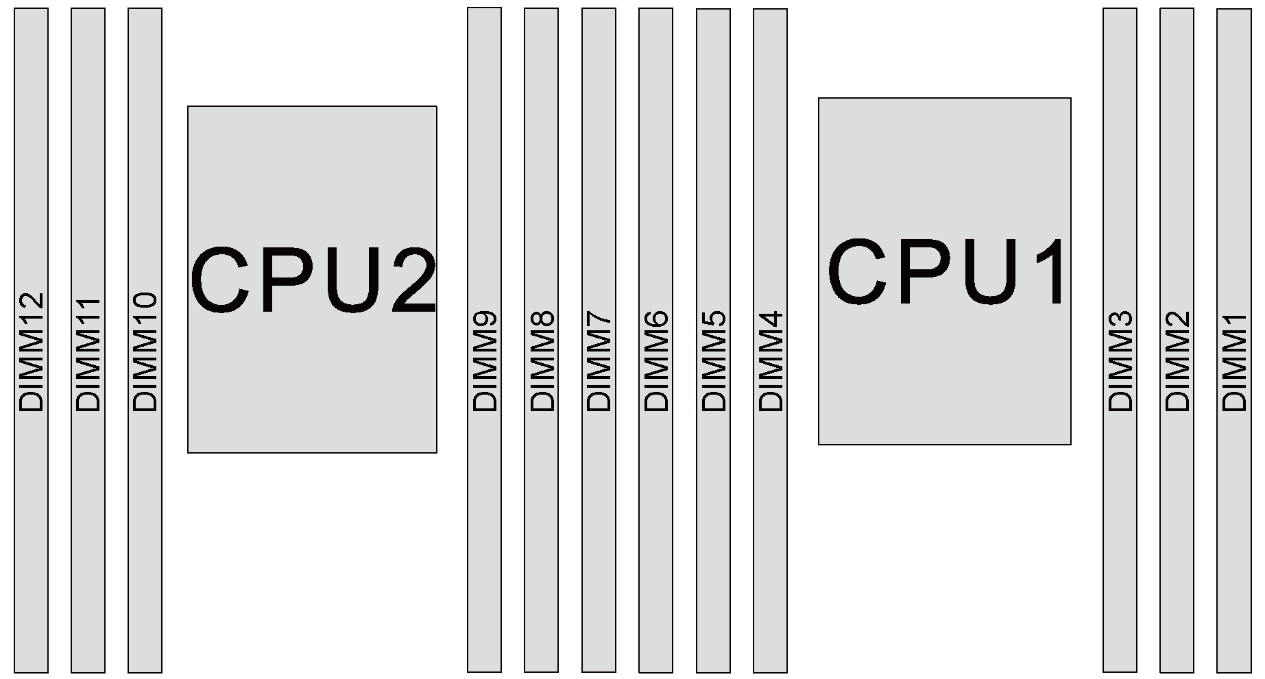
If there are three identical memory modules to be installed for CPU1, and the three memory modules have the same Lenovo part number, install the three memory modules in slots 1, 2, and 3.
If there are three identical memory modules to be installed for CPU2, and the three memory modules have the same Lenovo part numbers, install the three memory modules in slots 7, 8, and 9.
| Total memory modules | Processor 2 | Processor 1 | Total memory modules | ||||||||||
|---|---|---|---|---|---|---|---|---|---|---|---|---|---|
| 12 | 11 | 10 | 9 | 8 | 7 | 6 | 5 | 4 | 3 | 2 | 1 | ||
| 2 | 9 | 3 | 2 | ||||||||||
| 3 | 9 | 4 | 3 | 3 | |||||||||
| 4 | 10 | 9 | 4 | 3 | 4 | ||||||||
| 5 | 10 | 9 | 4 | 3 | 2 | 5 | |||||||
| 6 | 10 | 9 | 8 | 4 | 3 | 2 | 6 | ||||||
| 7 | 10 | 9 | 8 | 5 | 4 | 3 | 2 | 7 | |||||
| 8 | 11 | 10 | 9 | 8 | 5 | 4 | 3 | 2 | 8 | ||||
| 9 | 11 | 10 | 9 | 8 | 5 | 4 | 3 | 2 | 1 | 9 | |||
| 10 | 11 | 10 | 9 | 8 | 7 | 5 | 4 | 3 | 2 | 1 | 10 | ||
| 11 | 11 | 10 | 9 | 8 | 7 | 6 | 5 | 4 | 3 | 2 | 1 | 11 | |
| 12 | 12 | 11 | 10 | 9 | 8 | 7 | 6 | 5 | 4 | 3 | 2 | 1 | 12 |
Mirroring mode
All memory modules to be installed must be the same type with the same capacity, frequency, voltage, and rank.
Partial Memory Mirroring is a sub-function of memory mirroring. It requires following the memory installation order of memory mirroring mode.
| Total memory modules | Processor 1 | Total memory modules | |||||
|---|---|---|---|---|---|---|---|
| 6 | 5 | 4 | 3 | 2 | 1 | ||
| 2 | 3 | 2 | 2 | ||||
| 3 | 3 | 2 | 1 | 3 | |||
| 4 | 5 | 4 | 3 | 2 | 4 | ||
| 6 | 6 | 5 | 4 | 3 | 2 | 1 | 6 |
| Total memory modules | Processor 2 | Processor 2 | Total memory modules | ||||||||||
|---|---|---|---|---|---|---|---|---|---|---|---|---|---|
| 12 | 11 | 10 | 9 | 8 | 7 | 6 | 5 | 4 | 3 | 2 | 1 | ||
| 4 | 9 | 8 | 3 | 2 | 4 | ||||||||
| 5 | 9 | 8 | 3 | 2 | 1 | 5 | |||||||
| 6 | 9 | 8 | 7 | 3 | 2 | 1 | 6 | ||||||
| 8 | 11 | 10 | 9 | 8 | 5 | 4 | 3 | 2 | 8 | ||||
| 9 | 9 | 8 | 7 | 6 | 5 | 4 | 3 | 2 | 1 | 9 | |||
| 10 | 11 | 10 | 9 | 8 | 6 | 5 | 4 | 3 | 2 | 1 | 10 | ||
| 12 | 12 | 11 | 10 | 9 | 8 | 7 | 6 | 5 | 4 | 3 | 2 | 1 | 12 |
Rank sparing mode
All memory modules to be installed must be the same type with the same capacity, frequency, voltage, and number of ranks.
Single-rank memory modules do not support rank sparing mode.
| Total memory modules | Processor 1 | Total memory modules | |||||
|---|---|---|---|---|---|---|---|
| 6 | 5 | 4 | 3 | 2 | 1 | ||
| 1 | 3 | 1 | |||||
| 2 | 4 | 3 | 2 | ||||
| 3 | 4 | 3 | 2 | 3 | |||
| 4 | 5 | 4 | 3 | 2 | 4 | ||
| 5 | 5 | 4 | 3 | 2 | 1 | 5 | |
| 6 | 6 | 5 | 4 | 3 | 2 | 1 | 6 |
| Total memory modules | Processor 2 | Processor 1 | Total memory modules | ||||||||||
|---|---|---|---|---|---|---|---|---|---|---|---|---|---|
| 12 | 11 | 10 | 9 | 8 | 7 | 6 | 5 | 4 | 3 | 2 | 1 | ||
| 2 | 9 | 3 | 2 | ||||||||||
| 3 | 9 | 4 | 3 | 3 | |||||||||
| 4 | 10 | 9 | 4 | 3 | 4 | ||||||||
| 5 | 10 | 9 | 4 | 3 | 2 | 5 | |||||||
| 6 | 10 | 9 | 8 | 4 | 3 | 2 | 6 | ||||||
| 7 | 10 | 9 | 8 | 5 | 4 | 3 | 2 | 7 | |||||
| 8 | 11 | 10 | 9 | 8 | 5 | 4 | 3 | 2 | 8 | ||||
| 9 | 11 | 10 | 9 | 8 | 5 | 4 | 3 | 2 | 1 | 9 | |||
| 10 | 11 | 10 | 9 | 8 | 7 | 5 | 4 | 3 | 2 | 1 | 10 | ||
| 11 | 11 | 10 | 9 | 8 | 7 | 6 | 5 | 4 | 3 | 2 | 1 | 11 | |
| 12 | 12 | 11 | 10 | 9 | 8 | 7 | 6 | 5 | 4 | 3 | 2 | 1 | 12 |