卸下 E3.S 硬盘仓和背板
按照本节中的说明卸下 E3.S 硬盘仓和背板。
关于本任务
过程
- 卸下 E3.S 1T 硬盘仓。注无内板的 E3.S 挡板用于遮盖装有 E3.S 1T 硬盘仓的空间。为了确保正常散热和空气流通,请务必在开启服务器之前装回 E3.S 1T 硬盘仓和相应的 E3.S 挡板。如果使用无内板的 E3.S 挡板遮盖无 E3.S 1T 硬盘仓的空间,可能会在运行过程中损坏服务器组件。
 打开滑锁以松开硬盘仓。
 将硬盘仓从机箱中抽出。
图 1. 卸下 E3.S 1T 硬盘仓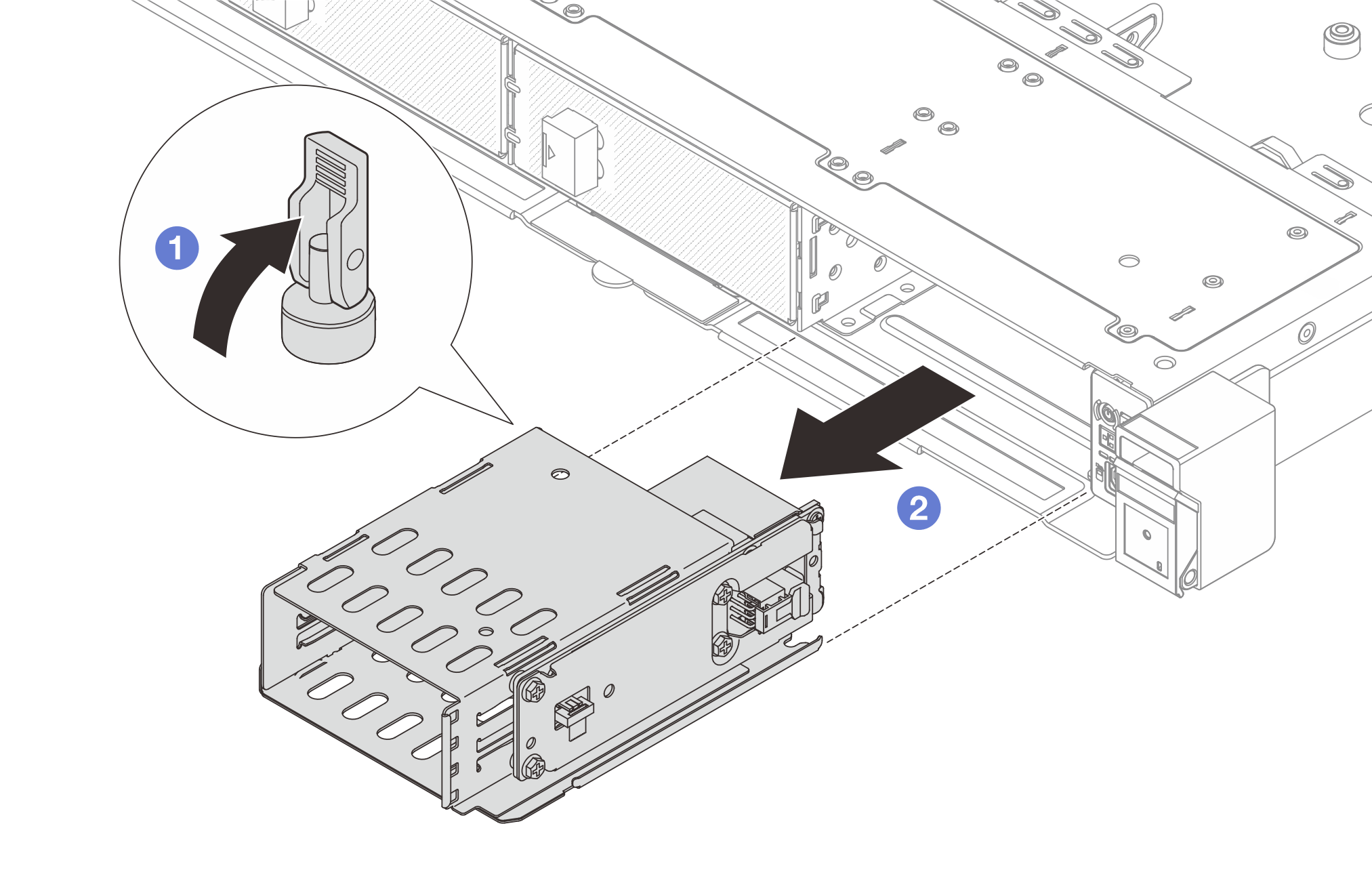
- 从 E3.S 1T 硬盘仓上卸下背板组合件。
- 松开固定背板组合件的四颗螺钉。
- 将背板组合件从硬盘仓上取下。
图 2. 卸下背板组合件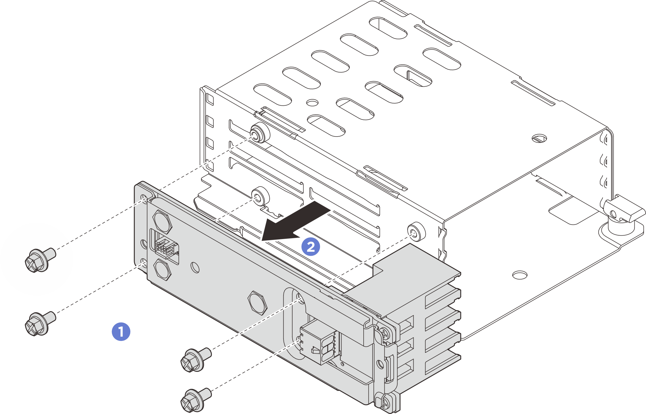
提供反馈