Install a 2.5-/3.5-inch hot-swap drive
Follow instructions in this section to install a 2.5-inch or 3.5-inch hot-swap drive.
About this task
Read Installation Guidelines and Safety inspection checklist to ensure that you work safely.
Touch the static-protective package that contains the drive to any unpainted metal surface on the solution; then, remove the drive from the package and place it on a static-protective surface.
Make sure you save the data on your drive, especially if it is part of a RAID array, before you remove it from the server.
To avoid damage to the drive connectors, make sure that the server top cover is in place and fully closed whenever you install or remove a drive.
To make sure that there is adequate system cooling, do not operate the server for more than two minutes without either a drive or a drive bay filler installed in each bay.
Before you make changes to drives, drive controllers (including controllers that are integrated on the system board), drive backplanes, or drive cables, back up all important data that is stored on drives.
Before you remove any component of a RAID array (drive, RAID card, etc.), back up all RAID configuration information.
- Locate the documentation that comes with the drive and follow those instructions in addition to the instructions in this chapter.
- The electromagnetic interference (EMI) integrity and cooling of the solution are protected by having all bays and PCI and PCIe slots covered or occupied. When you install a drive, PCI, or PCIe adapter, save the EMC shield and filler panel from the bay or PCI or PCIe adapter slot cover in the event that you later remove the device.
- For a complete list of supported optional devices for the server, see Lenovo ServerProven website.
- Depending on your server configuration for 4-DW GPU Model, the following drive types can be installed into each drive cage with their corresponding drive bay numbers:
Up to eight 2.5-inch SAS/SATA/NVMe drives
Figure 1. 2.5-inch drive bay numbering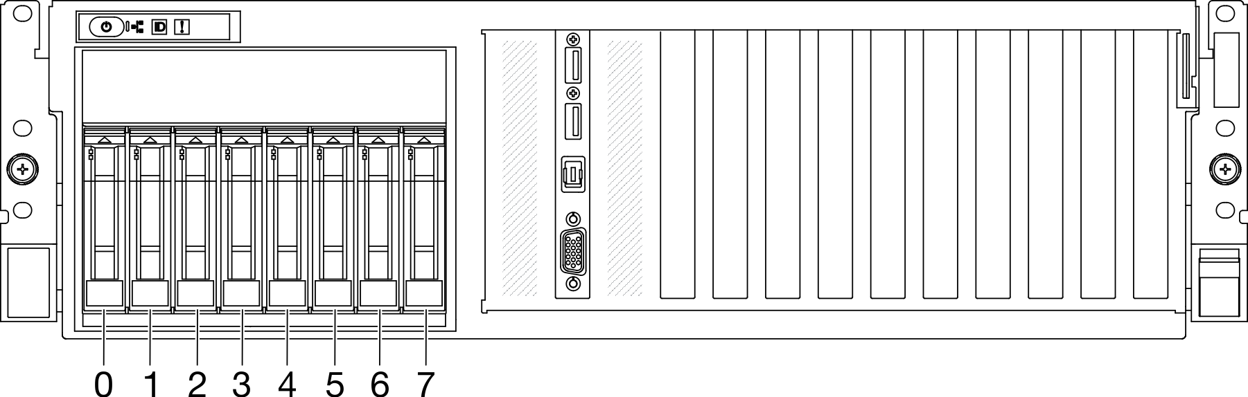
Up to four 3.5-inch SATA drives
Figure 2. 3.5-inch drive bay numbering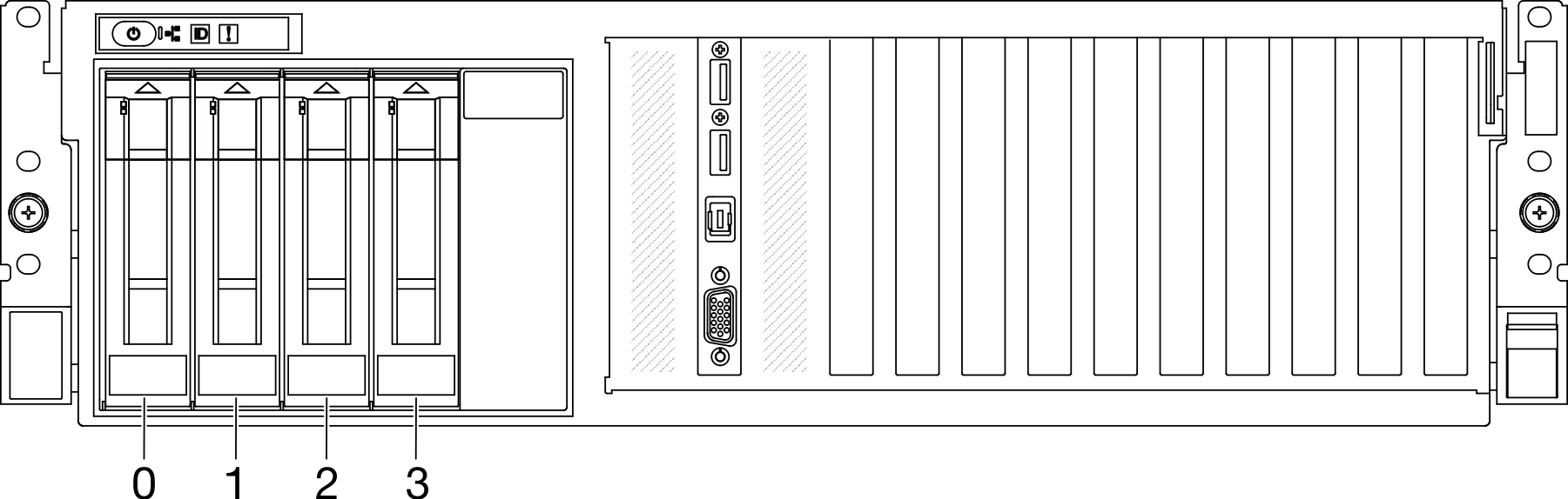
Procedure
- Based on your configuration, follow the corresponding procedures to install a 2.5-inch or 3.5-inch hot-swap drive.
Install a 2.5-inch hot-swap drive:
NoteIf a drive bay filler is installed in the drive bay, pull the release lever on the filler and slide it out of the server. Make sure that the drive handle is in the open position. Then, align the drive with the guide rails in the bay and gently push the drive into the bay until the drive stops.
 Rotate the drive handle to the fully closed position until the handle latch clicks.Figure 3. Installing a 2.5-inch hot-swap drive
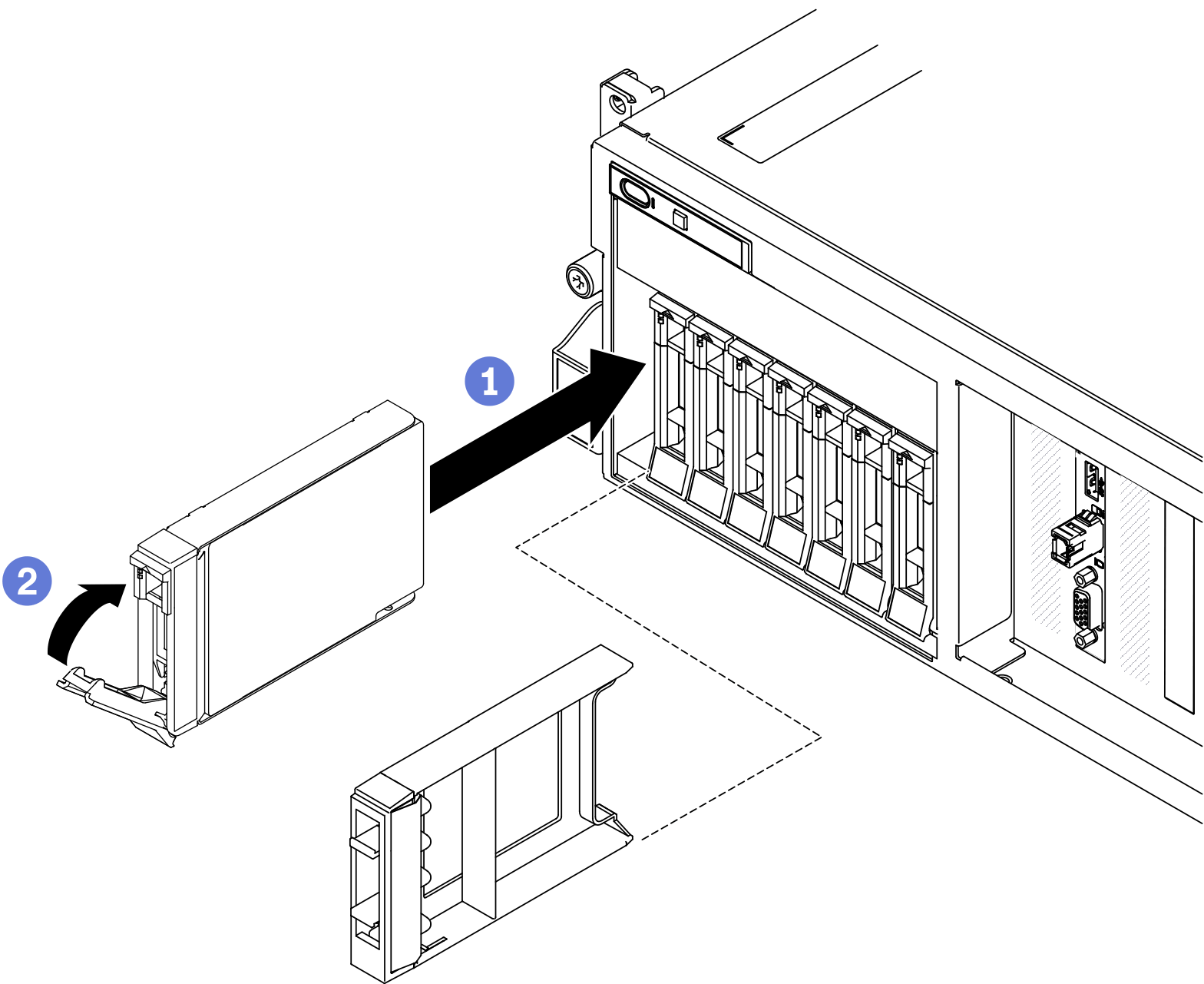
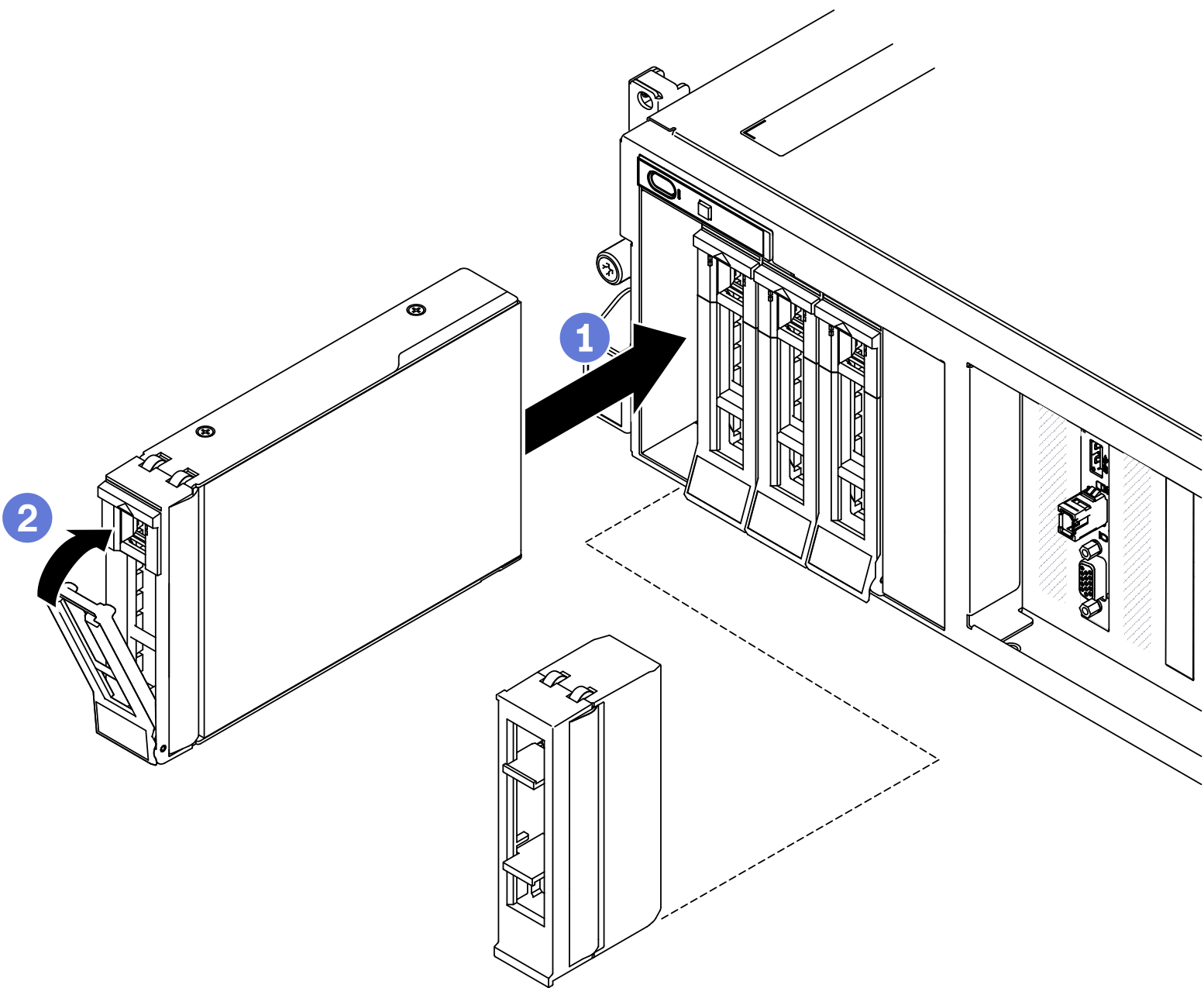
Install a 3.5-inch hot-swap drive:
NoteIf a drive bay filler is installed in the drive bay, pull the release lever on the filler and slide it out of the server.- Make sure that the drive handle is in the open position. Then, align the drive with the guide rails in the bay and gently push the drive into the bay until the drive stops.
- Rotate the drive handle to the fully closed position until the handle latch clicks.Figure 4. Installing a 3.5-inch hot-swap drive
After you finish
- Check the drive status LED to verify that the drive is operating correctly.
If the yellow drive status LED of a drive is lit continuously, that drive is faulty and must be replaced.
If the green drive activity LED is flashing, the drive is being accessed.
If the server is configured for RAID operation through a ThinkSystem RAID adapter, you might have to reconfigure your disk arrays after you install drives. See the ThinkSystem RAID adapter documentation for additional information about RAID operation and complete instructions for using ThinkSystem RAID adapter.
If you have installed 2.5-inch drive backplane with U.3 NVMe drives for Trimode. Enable U.3 x1 mode for the selected drive slots on the backplane through the XCC web GUI. See U.3 NVMe drive can be detected in NVMe connection, but cannot be detected in Tri-mode.
Demo video