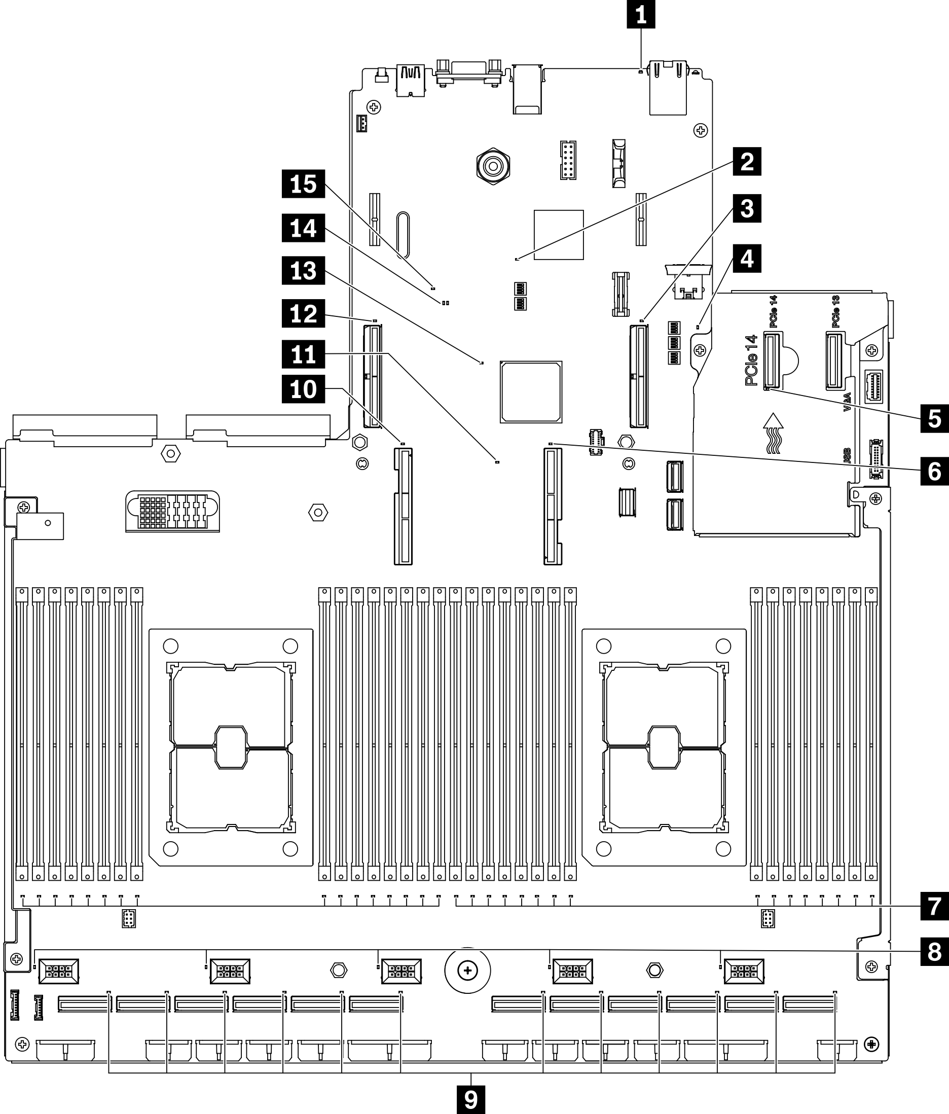
System-board LEDs

The following illustrations show the light-emitting diodes (LEDs) on the system board.

Press the power button to light the LEDs on the system board when the power source has been removed from the server.

Figure 1. System-board LEDs
System-board LEDs
Table 1. System board LEDs description and actions.
LEDDescription and actions
1 System error LED (yellow)LED on: an error has occurred. Complete the following steps:
  • Check the identification LED and check log LED and follow the instructions.

  • Check the Lenovo XClarity Controller event log and the system error log for information about the error.

  • Save the log if necessary, and clear the log afterwards.

2 XCC heartbeat LED (green)This LED indicates XCC heartbeat and boot process:
  • LED blinking fast: XCC code is in the loading process.

  • LED going off momentarily: XCC code has loaded completely.

  • LED going off momentarily and then starts blinking slowing: XCC is fully operational. You can now press the power-control button to power on the server.

3 PCIe slot 15 error LEDLED on: an error has occurred to the PCIe slot the LED represents. Complete the following steps:
  1. Make sure the cable is connected to the appropriate downstream PCIe riser, drive backplane, or OCP adapter.

  2. Make sure both ends of the cable are securely seated in the PCIe slots.

  3. Replace the cable.

  4. (Trained technician only) replace the system board. See System board replacement (trained technician only).

4 UEFI ROM heartbeat LED (green)This LED indicated the UEFI ROM status:
  • LED blinking: the UEFI ROM is in normal operation.

  • LED off: the UEFI ROM is not loaded or in recovery.

5 OCP error LEDLED on: an error has occurred to the OCP slot the LED represents. Complete the following steps:
  • Make sure the PCIe cable is connected to the appropriate downstream PCIe slot 15-16 or PCIe connector 1-12.

  • Make sure both ends of the cable are securely seated in the PCIe slots.

  • Replace the cable.

  • (Trained technician only) replace the system board. See System board replacement (trained technician only).

6 Processor 1 error LEDLED on: an error has occurred to the processor the LED represents.
7 DIMM 1-32 error LED (amber)LED on: an error has occurred to the DIMM the LED represents.
8 Fan 1-5 error LEDLED on: an error has occurred to the fan the LED represents.
9 PCIe connector 1-12 error LEDLED on: an error has occurred to the PCIe connector the LED represents. Complete the following steps:
  1. Make sure the cable is connected to the appropriate downstream PCIe riser, drive backplane, or OCP adapter.

  2. Make sure both ends of the cable are securely seated in the PCIe slots.

  3. Replace the cable.

  4. (Trained technician only) replace the system board. See System board replacement (trained technician only).

10 Processor 2 error LEDLED on: An error has occurred to the processor the LED represents.
11 Lightpath power LEDThis LED indicates if there is sufficient power to lit the LEDs when light path button is pressed while the system is not connected to the power.
12 PCIe slot 16 error LEDLED on: an error has occurred to the PCIe slot the LED represents. Complete the following steps:
  1. Make sure the cable is connected to the appropriate downstream PCIe riser, drive backplane, or OCP adapter.

  2. Make sure both ends of the cable are securely seated in the PCIe slots.

  3. Replace the cable.

  4. (Trained technician only) replace the system board. See System board replacement (trained technician only).

13 FPGA heartbeat error LED (green)This LED indicates power-on and power-off sequencing.
14 UEFI valid LEDThe LED indicates the UEFI flash content verification result.
  • LED on: UEFI flash contents verification passed.

  • LED off: UEFI flash contents verification failed.

15 PFR error LEDThe LED indicated the PFR (Platform Firmware Resilience) error.