GPU processor mapping and adapter population rules (3-slot PCIe expansion cage)
Use the information in this topic to understand adapter-to-processor mapping and the GPU adapter population order for adapters in the 3-slot PCIe expansion cage.
Note
PCIe expansion cage 1 and PCIe expansion cage 2 must be the same type, either 4-slot PCIe expansion cages or 3-slot PCIe expansion cages
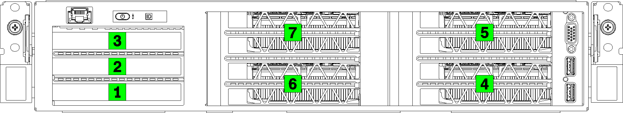
The following figure illustrates the numbering for the PCIe slots in the server (when 3-slot PCIe expansion cages are installed).
Note
Only double-width full-height, full-length (FHFL) GPUs are supported in the 3-slot PCIe expansion cage.
Figure 1. Numbering of the PCIe slots on the server
The following table shows how the PCIe adapter slots are mapped to the system processors.
| Adapter slot | Description | Processor mapping |
|---|---|---|
| I/O expansion cage | ||
| Slot 1 | PCIe 3.0 x16 (full-height, half-length). Typically, a network adapter is installed in this slot. | 1 |
| Slot 2 | PCIe 3.0 x16 (full-height, half-length). Typically, a RAID adapter or a network adapter is installed in this slot. | 2 |
| Slot 3 | PCIe 3.0 x4 (full-height, half-length). Typically, a 1GbE network adapter is installed in this slot. | Onboard chipset, also known as the Platform Controller Hub (PCH) |
| 3-slot PCIe expansion cage 1 | ||
| Slot 4 | PCIe 3.0 x16 for a GPU (full-height, full-length, double-width) | 1 |
| Slot 5 | PCIe 3.0 x16 for a GPU (full-height, full-length, double-width) | 1 |
| 3-slot PCIe expansion cage 2 | ||
| Slot 6 | PCIe 3.0 x16 for a GPU (full-height, full-length, double-width) | 2 |
| Slot 7 | PCIe 3.0 x16 for a GPU (full-height, full-length, double-width) | 2 |
| System board | ||
| Slot 8 (internal) | M.2 | Onboard chipset, also known as the Platform Controller Hub (PCH) |
The following table defines the population order for the GPU adapters in the PCIe expansion cages 1 and 2.
| Number of PCIe adapters | Concentrated | Distributed |
|---|---|---|
| 1 GPU adapter | Slot 4 | Slot 4 |
| 2 GPU adapters | Slot 4, slot 5 | Slot 4, slot 6 |
| 3 GPU adapters | Slot 4, slot 5, slot 6 | Slot 4, slot 5, slot 6 |
| 4 GPU adapters | Slot 4, slot 5, slot 6, slot 7 | Slot 4, slot 5, slot 6, slot 7 |
Give documentation feedback