Kabelführung für E/A-Erweiterungsplatinenmodul an der Vorderseite
In diesem Abschnitt wird die Kabelführung für die E/A-Erweiterungsplatine an der Vorderseite beschrieben.
Wählen Sie je nach Konfiguration den entsprechenden Kabelführungsplan aus:
Konfiguration mit direkter GPU-Stromversorgungsplatine – Konfigurationen 1, 2 und 20
Abbildung 1. Kabelführung für E/A-Erweiterungsplatinenmodul an der Vorderseite
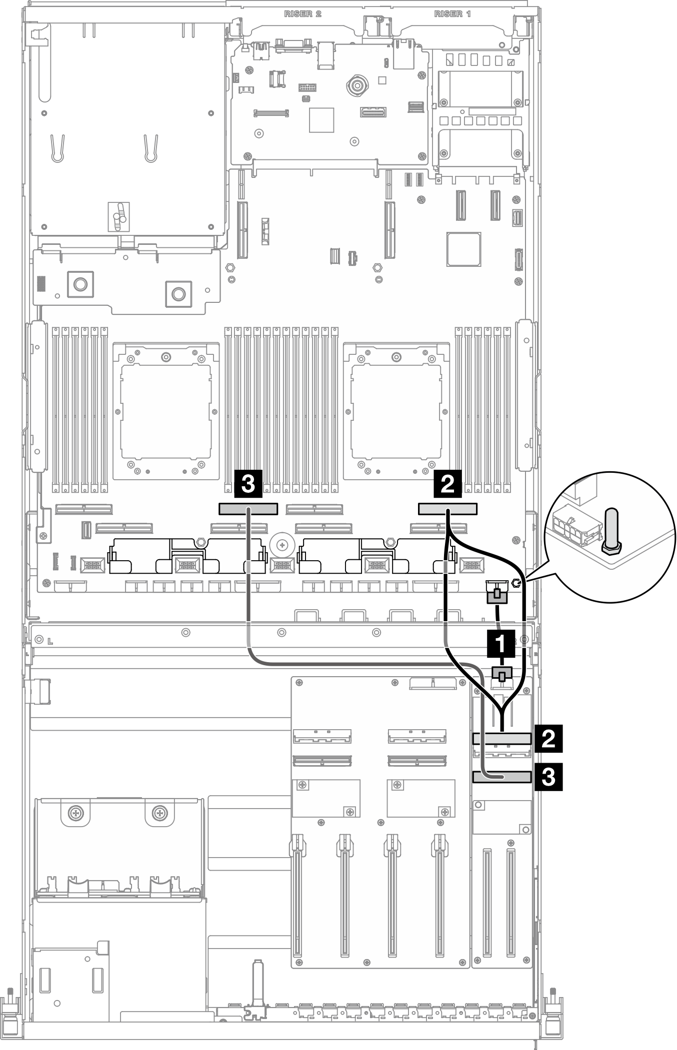
| Kabel | Vom | Zu |
|---|---|---|
| 1 | E/A-Erweiterungsplatine an der Vorderseite: Netzteilanschluss | Systemplatinenbaugruppe: Netzteilanschluss für vordere Adapterkarte |
| 2 | E/A-Erweiterungsplatine an der Vorderseite: MCIO-Anschluss A | Systemplatinenbaugruppe: PCIe-Anschluss 2 |
| 3 | E/A-Erweiterungsplatine an der Vorderseite: MCIO-Anschluss B | Systemplatinenbaugruppe: PCIe-Anschluss 6 |
Konfiguration mit geschalteter GPU-Stromversorgungsplatine – Konfigurationen 5 und 14
Abbildung 2. Kabelführung für die E/A-Erweiterungsplatine an der Vorderseite
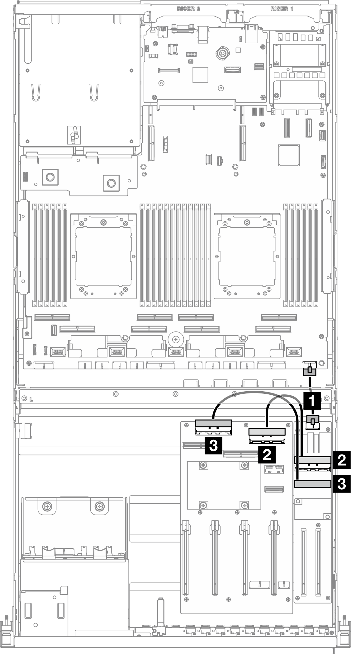
| Kabel | Vom | Zu |
|---|---|---|
| 1 | E/A-Erweiterungsplatine an der Vorderseite: Netzteilanschluss | Systemplatinenbaugruppe: Netzteilanschluss für vordere Adapterkarte |
| 2 | E/A-Erweiterungsplatine an der Vorderseite: MCIO-Anschluss A | GPU-Stromversorgungsplatine: MCIO-Anschluss D |
| 3 | E/A-Erweiterungsplatine an der Vorderseite: MCIO-Anschluss B | GPU-Stromversorgungsplatine: MCIO-Anschluss C |
Feedback geben