Kabelführung für OCP-Modul
Verwenden Sie diesen Abschnitt, um die Kabelführung für das OCP-Modul nachzuvollziehen.
Wählen Sie je nach Konfiguration den entsprechenden Kabelführungsplan aus:
Konfiguration mit direkter GPU-Stromversorgungsplatine – Konfiguration 1
Abbildung 1. Kabelführung für OCP-Modul
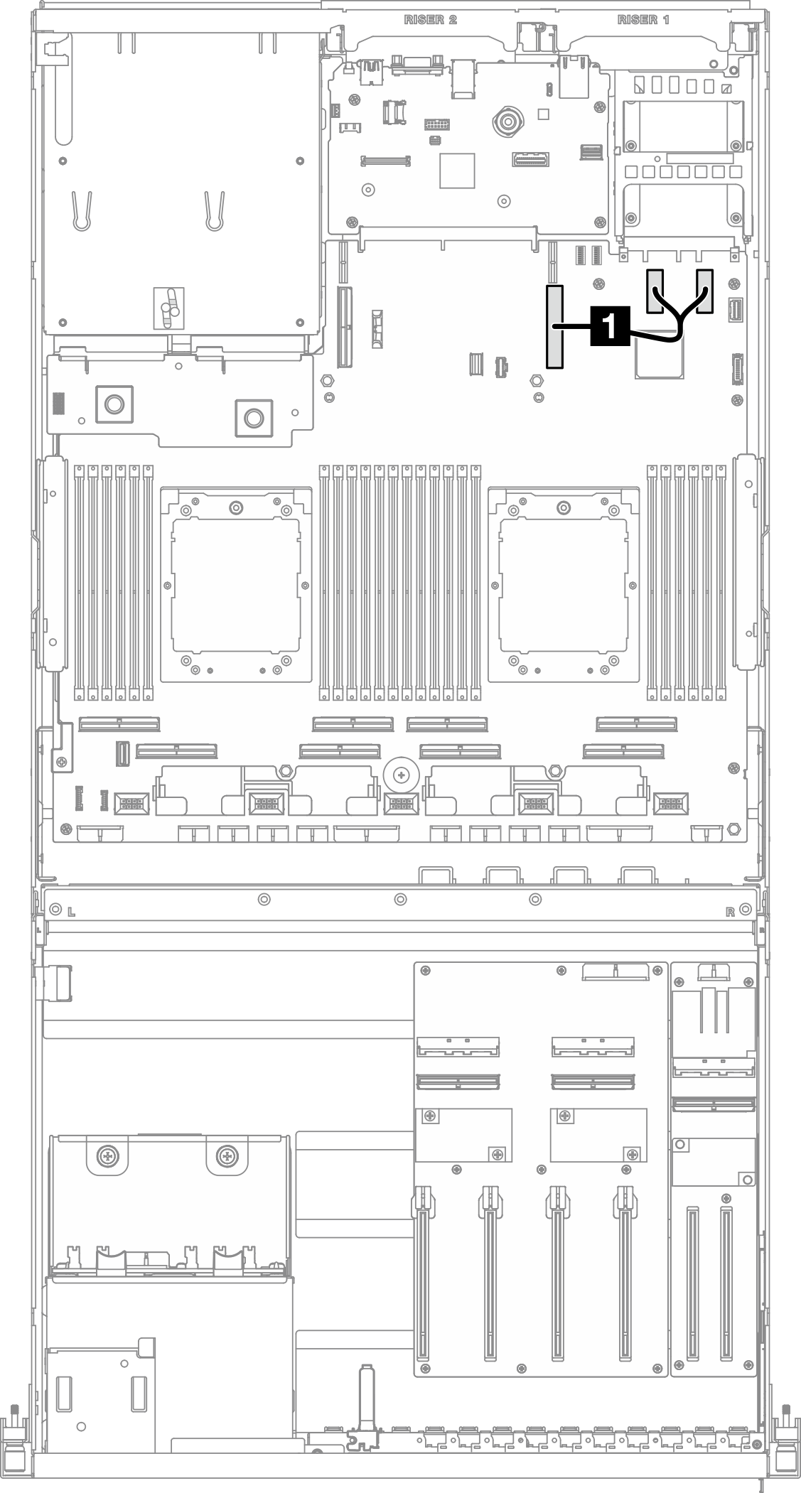
| Kabel | Vom | Zu |
|---|---|---|
| 1 | Systemplatinenbaugruppe: PCIe-Anschlüsse 11 und 12 | Systemplatinenbaugruppe: PCIe-Anschluss 9 |
Konfiguration mit geschalteter GPU-Stromversorgungsplatine – Konfigurationen 5 und 14
Abbildung 2. Kabelführung für OCP-Modul
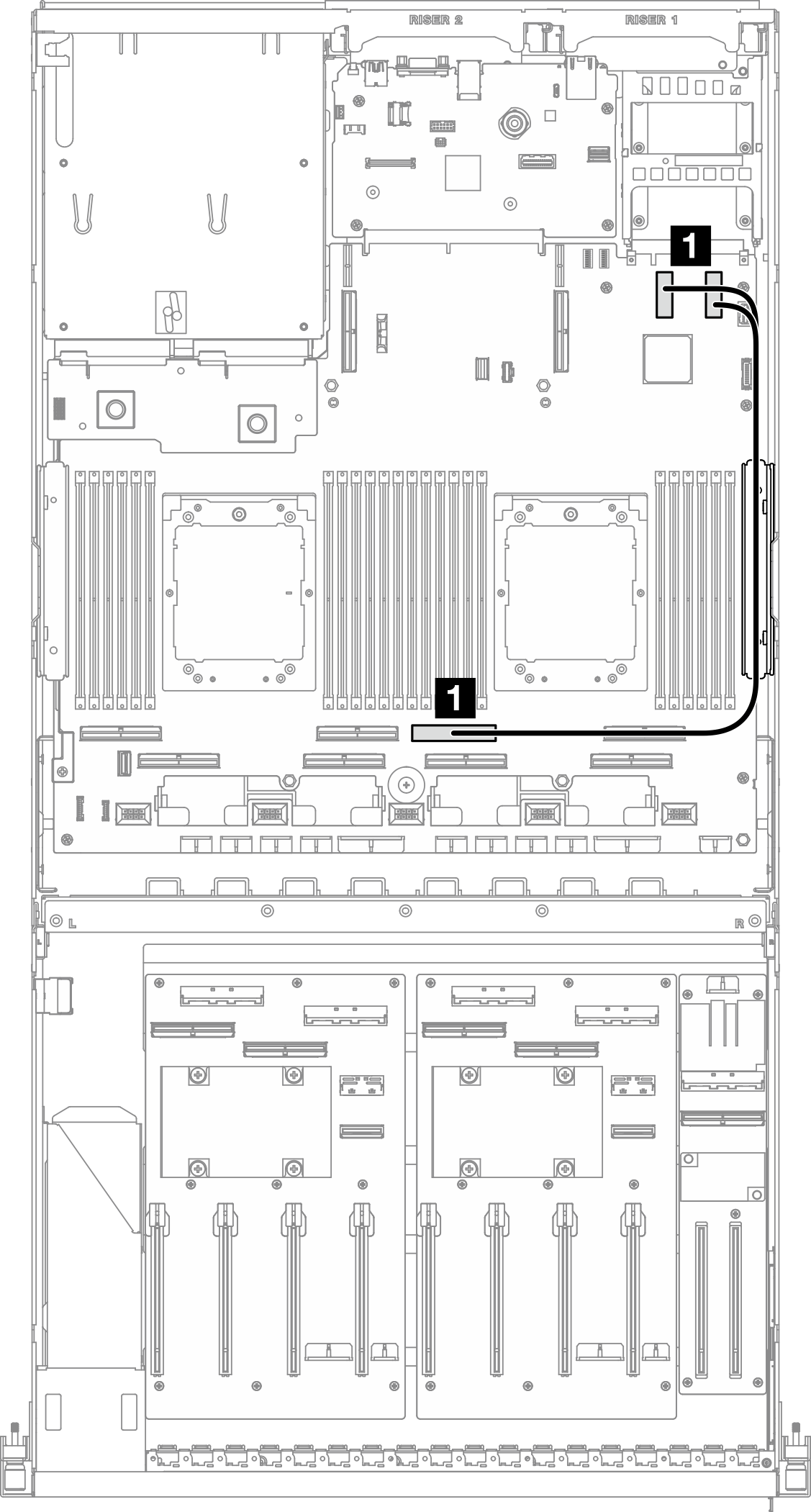
| Kabel | Vom | Zu |
|---|---|---|
| 1 | Systemplatinenbaugruppe: PCIe-Anschlüsse 11 und 12 | Systemplatinenbaugruppe: PCIe-Anschluss 4 |
Feedback geben