正面 I/O 模組和整合式診斷面板纜線佈線
使用本節瞭解正面 I/O 模組和整合式診斷面板的纜線佈線。
根據位置,選取對應的佈線方案:
在 2U 運算滑動箱中
註
確保依照指示將纜線穿過纜線導件。
圖 1. 正面 I/O 模組和整合式診斷面板纜線佈線
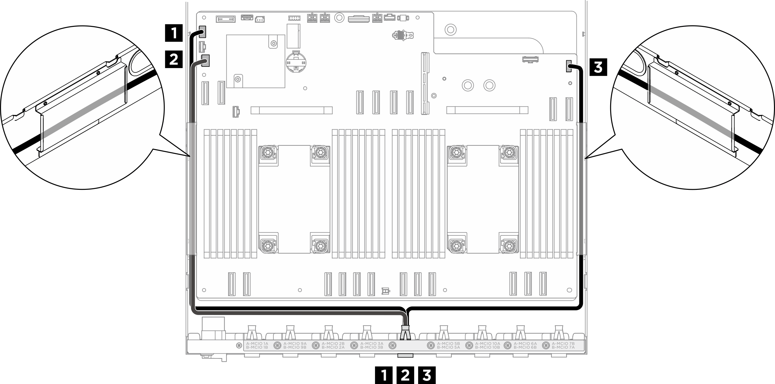
| 纜線 | 從 | 到 |
|---|---|---|
| 1 | 後方 PCIe 交換器纜線載具:USB/Mini DisplayPort 纜線 | 主機板:正面 USB/Mini DisplayPort 接頭 (FRONT IO1) |
| 2 | PCIe 交換器板:GPU 管理纜線 | 主機板:PCIe 開關側頻接頭 (PCIE SW SIDEBAND) |
| 3 | 後方 PCIe 交換器纜線載具:整合式診斷面板纜線 | 主機板:整合式診斷面板接頭 (FRONT IO2) |
如需在 PCIe 交換器板上進行 GPU 管理纜線佈線,請參閱PCIe 交換器板纜線佈線。
在 8U GPU 滑動箱中
圖 2. 正面 I/O 模組和整合式診斷面板纜線佈線
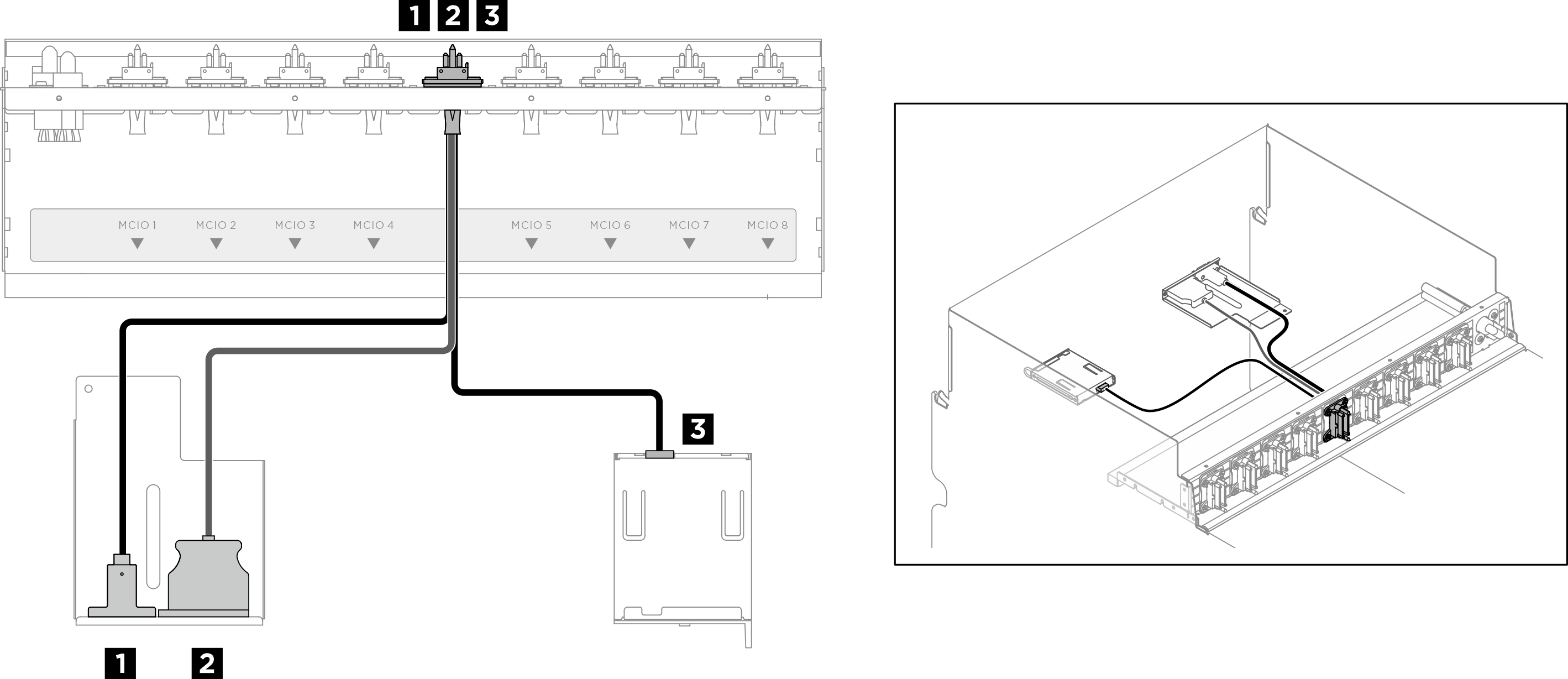
| 纜線 | 從 | 到 |
|---|---|---|
| 1 | 前方 PCIe 交換器纜線載具:Mini DisplayPort 纜線 | 正面 I/O 模組 |
| 2 | 前方 PCIe 交換器纜線載具:USB 纜線 | 正面 I/O 模組 |
| 3 | 前方 PCIe 交換器纜線載具:整合式診斷面板纜線 | 整合式診斷面板 |
提供意見回饋