Remover uma GPU B200 traseira
Siga as instruções nesta seção para remover uma GPU B200 traseira. O procedimento deve ser executado por um técnico treinado.
Sobre esta tarefa
- Leia Diretrizes de instalação e Lista de verificação de inspeção de segurança para garantir que esteja trabalhando de forma segura.
- Desligue o servidor e os dispositivos periféricos e desconecte os cabos de alimentação e todos os cabos externos. Consulte Desligar o servidor.
- Se o servidor estiver instalado em um rack, deslize o servidor para fora dos trilhos deslizantes do rack para acessar a tampa superior ou remover o chassi do rack. Consulte Remover o servidor do rack.
- Duas pessoas e um dispositivo de elevação no local que podem suportar até 400 lb (181 kg) são necessários para executar esse procedimento. Se você ainda não tiver um dispositivo de içamento disponível, a Lenovo oferece o Genie Lift GL-8 material lift que pode ser adquirido em Data Center Solution Configurator. Inclua o freio e a plataforma de carga ao pedir o Genie Lift GL-8 material lift.
- Uma chave de fenda de torque estará disponível para solicitação se você não tiver uma em mãos.
- Chave de fenda de cabeça Torx T15
- 2 x bit de extensão Torx T15 de 200 mm
- Chave de fenda de cabeça Phillips nº 1
- Chave de fenda de cabeça Phillips nº 2
- Pano de limpeza com álcool
- PCM B200
- B200 SXM6 PAD-1
- B200 SXM6 PAD-2
- Kit de serviço de GPU B200
- Antes de substituir o protetor putty/PCM, limpe suavemente a superfície do hardware com um pano de limpeza com álcool.
- Segure o protetor putty/PCM com cuidado para evitar deformação. Certifique-se de que nenhum orifício ou abertura do parafuso esteja bloqueado pelo protetor putty/PCM.
- Não use protetor putty/PCM vencido. Verifique a data de validade na embalagem do protetor putty/PCM. Se os protetores putty/PCM tiverem vencido, adquira novos para substituí-los adequadamente.
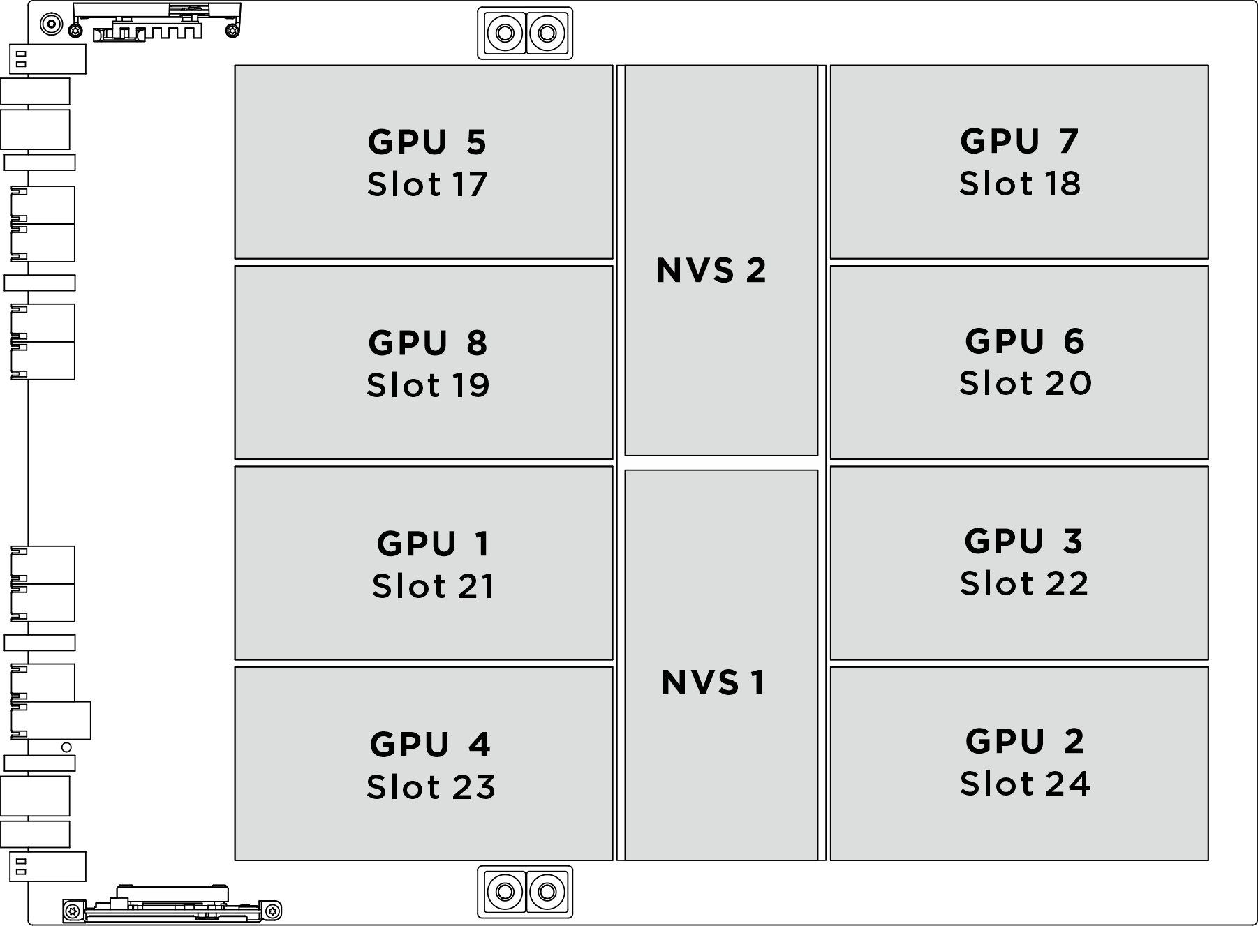
| Soquete de GPU físico | Numeração de slot no XCC | Número lógico em nvidia-smi |
|---|---|---|
GPU 1 | Slot 21 | 4 |
GPU 2 | Slot 24 | 7 |
GPU 3 | Slot 22 | 5 |
GPU 4 | Slot 23 | 6 |
GPU 5 | Slot 17 | 0 |
GPU 6 | Slot 20 | 3 |
GPU 7 | Slot 18 | 1 |
GPU 8 | Slot 19 | 2 |
Procedimento
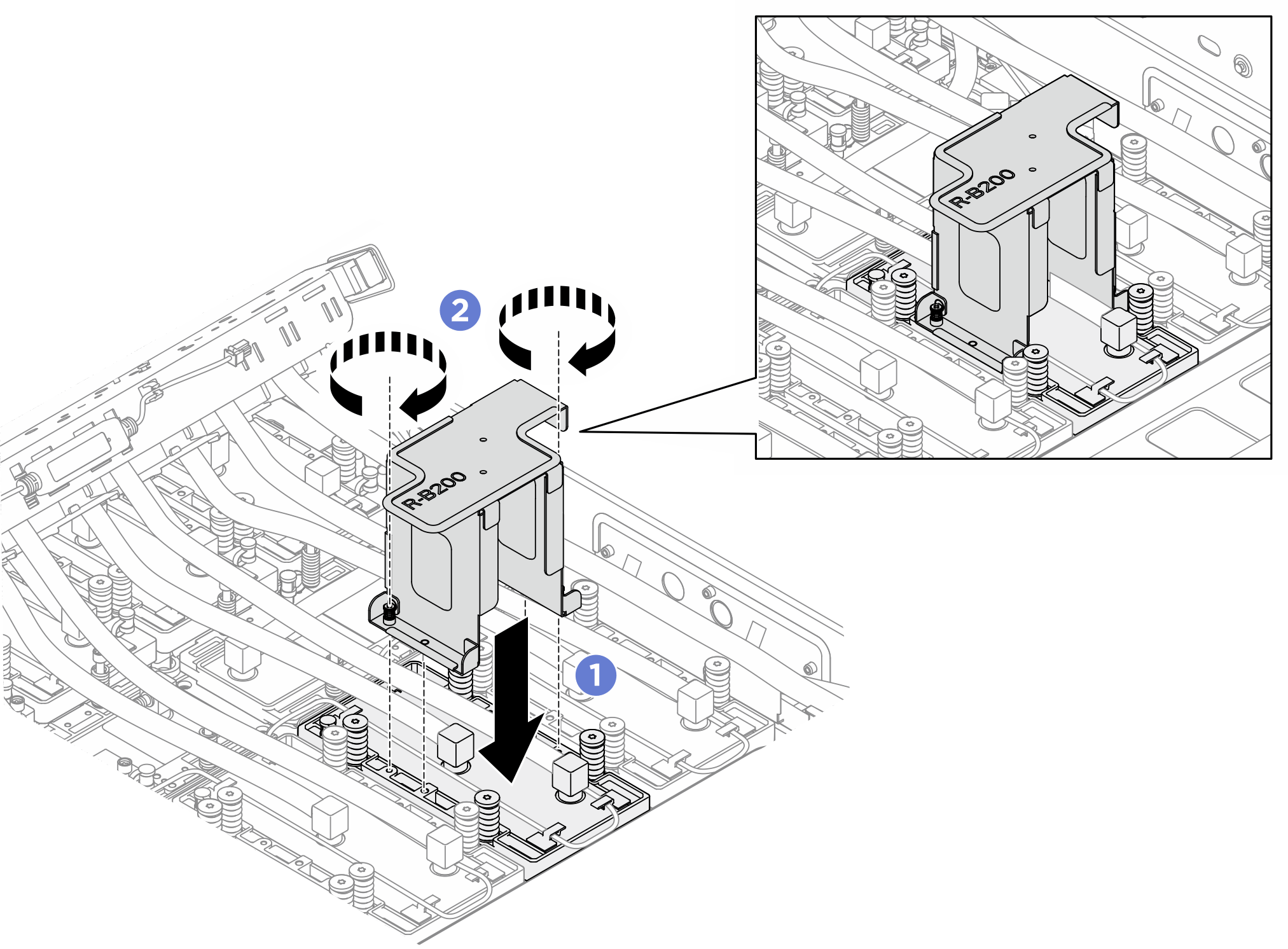
- Remova o suporte de apoio da gaiola do ventilador traseiro.
 Solte os oito parafusos M3 que prendem o suporte de apoio da gaiola do ventilador traseiro no chassi.
 Solte os quatro parafusos M3 que prendem o suporte de apoio da gaiola do ventilador traseiro na gaiola do ventilador.
 Segure o suporte de apoio da gaiola do ventilador traseiro para erguê-lo da gaiola do ventilador.
Figura 2. Removendo o suporte de apoio da gaiola do ventilador traseiro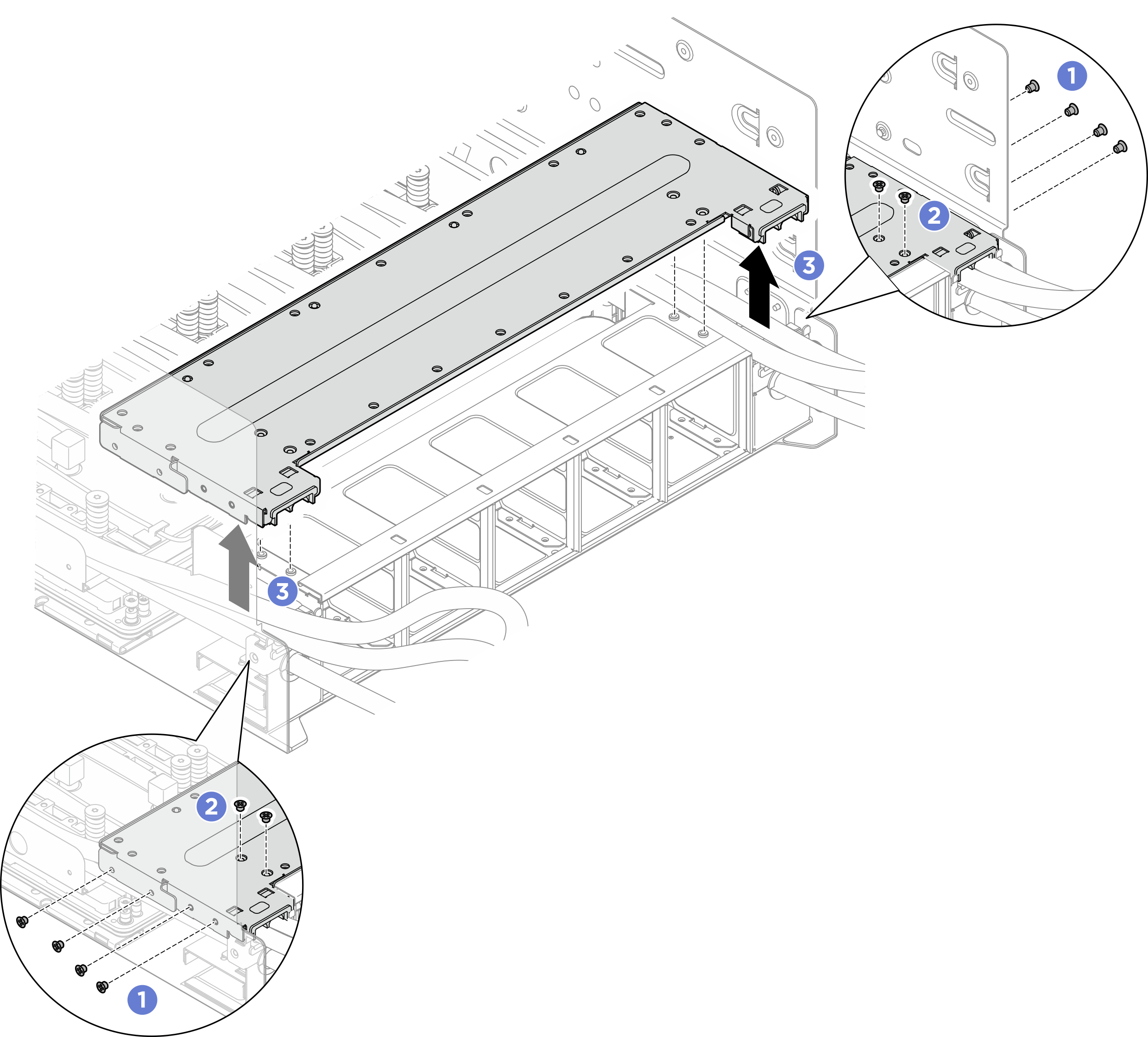
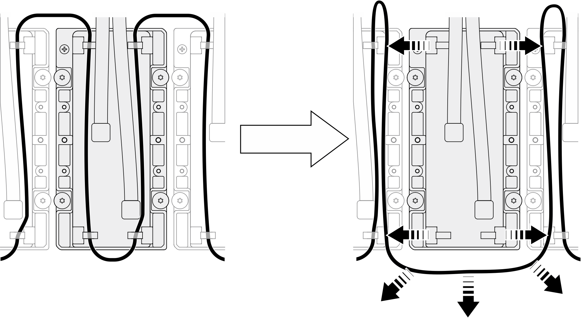
- Remova o cabo do módulo do sensor de vazamento das presilhas de cabos, afaste-os da placa fria e reinstale-o na placa fria adjacente.Figura 3. Removendo o cabo do módulo do sensor de vazamento
- Solte os parafusos em 360 graus seguindo a sequência de parafusos:
 especificada na etiqueta da placa fria e solte totalmente os quatro parafusos Torx T15 com uma chave de fenda de torque ajustada para o torque adequado.Nota
- Solte os parafusos com uma chave de fenda de torque ajustada para o torque adequado. Para referência, o torque necessário para que os parafusos fiquem totalmente soltos é de 5,3±0,212 polegadas-libras, 0,6±0,024 Newton-metros.
- Os parafusos prisioneiros devem estar completamente soltos antes de remover o módulo de placa fria.
- Siga a sequência de parafusos para evitar a inclinação da placa fria.
Figura 4. Removendo a placa fria da GPU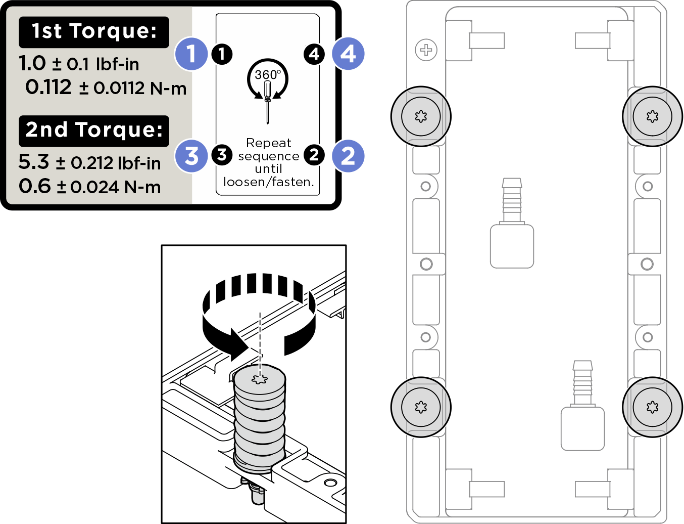 Nota
NotaSe necessário, use o parafuso disjuntor TIM para separar a placa fria da GPU. Solte totalmente todos os parafusos da placa fria antes de apertar o parafuso do disjuntor TIM.
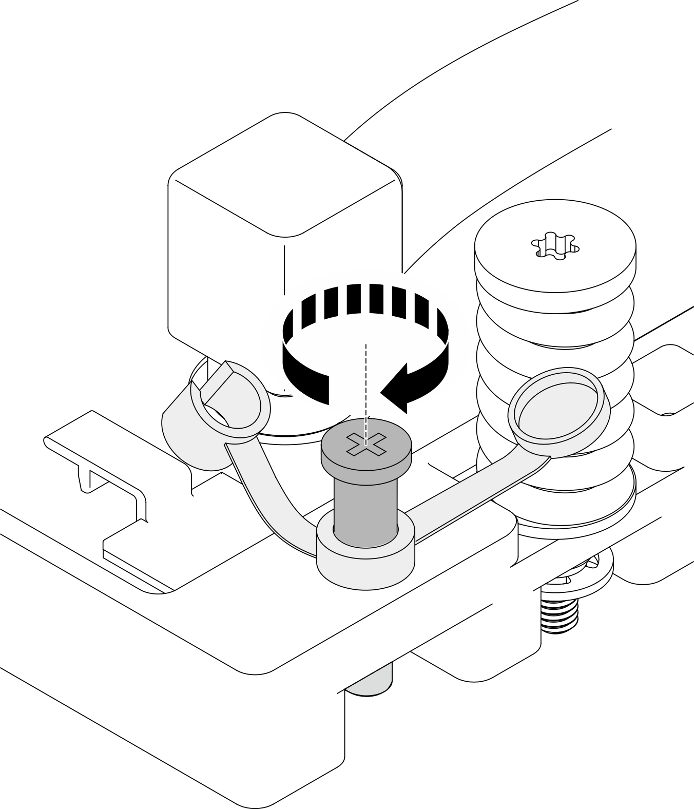
- Abra a tampa do parafuso do disjuntor TIM.

- Aperte o parafuso do disjuntor TIM para separar a placa fria da GPU.
Após o uso, devolva o parafuso do disjuntor TIM à sua posição original.
- Solte o parafuso do disjuntor TIM para devolvê-lo à sua posição inicial.
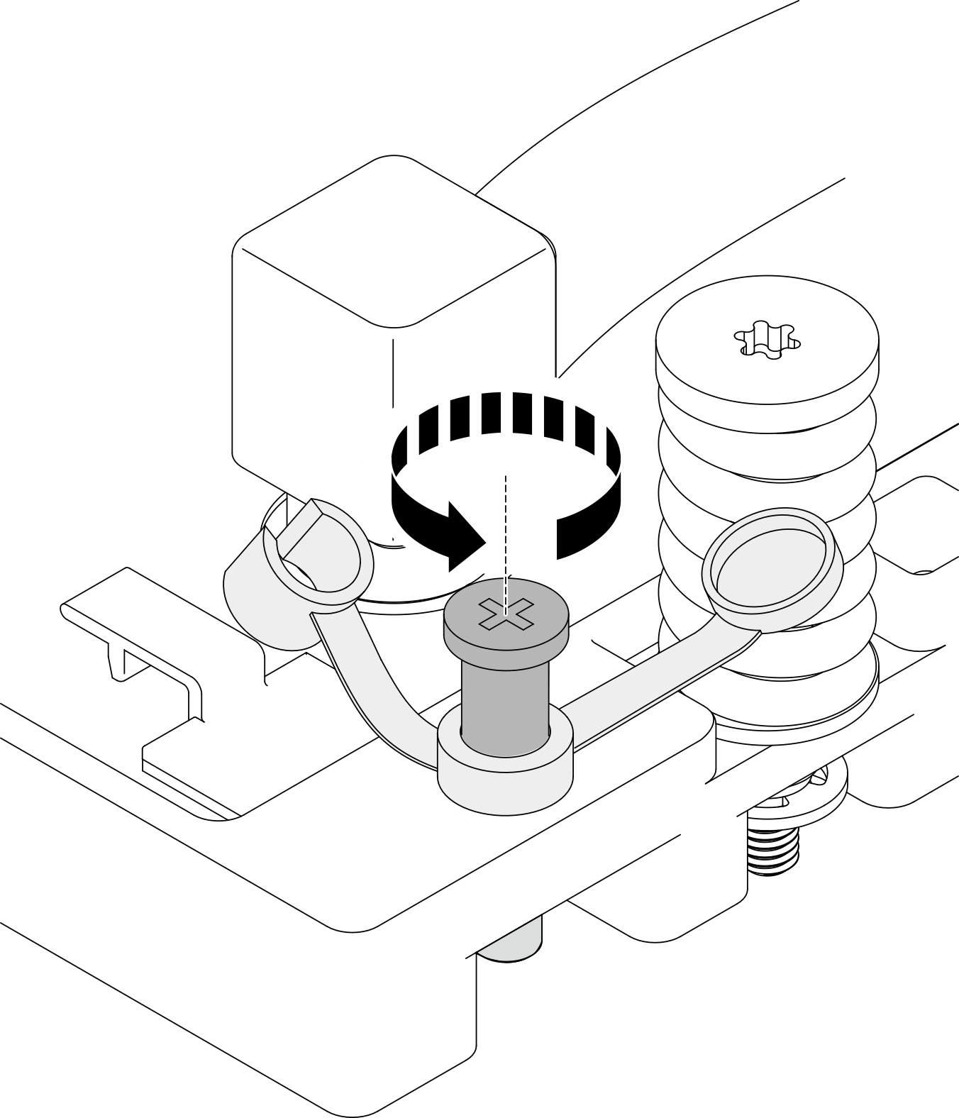
- Feche a tampa. Caso não seja possível fechar a tampa, será necessário soltar mais o parafuso do disjuntor TIM.
- Instale o suporte de serviço na placa fria da GPU traseira.
- Alinhe os dois pinos-guia na parte inferior do suporte de serviço com os orifícios dos parafusos na placa fria da GPU; em seguida, abaixe-o para a placa fria.
- Aperte os dois parafusos prisioneiros (PH1, 2 x M3, 0,5 Newton-metro, 4,3 libras-polegada) para prender o suporte de serviço na placa fria.Figura 5. Instalando o suporte de serviço na placa fria da GPU
 NotaEvite apertar o cabo do módulo do sensor de vazamento ao instalar o suporte.
- Instale o suporte de serviço e o conjunto de placa fria da GPU no coletor do módulo de placa fria da GPU B200 traseira.
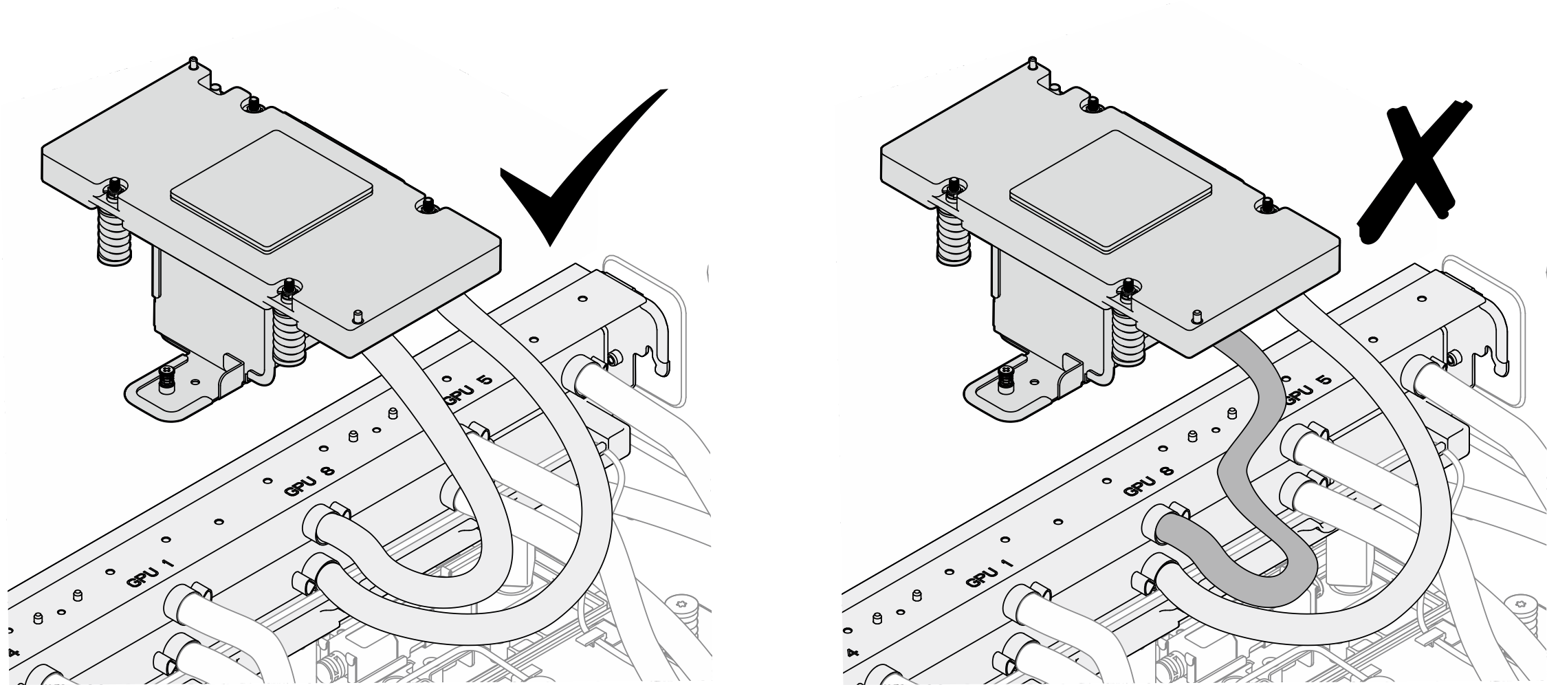
- Vire o suporte de serviço e o conjunto de placa fria da GPU; em seguida, alinhe o parafuso prisioneiro e os dois pinos-guia com o orifício do parafuso e orifícios-guia no coletor.NotaNão dobre as mangueiras para dentro para evitar danos por estresse nas articulações.
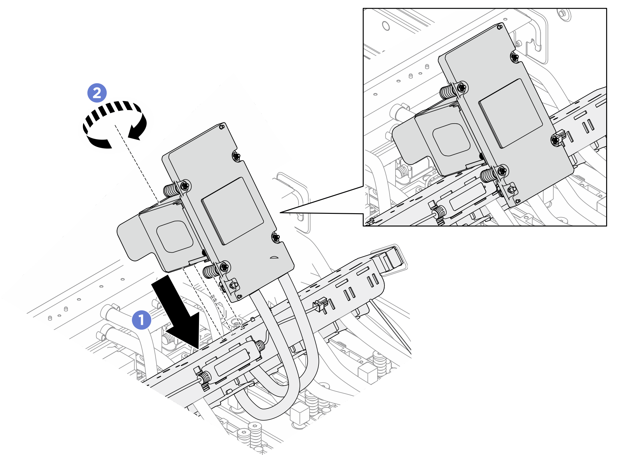
- Aperte o parafuso prisioneiro (PH1, 1 x M3, 0,5 newton-metro, 4,3 libras-polegadas) para fixar o suporte de serviço e o conjunto de placa fria da GPU no coletor.Figura 6. Instalando o suporte de serviço e o conjunto de placa fria da GPU
 NotaInstale o suporte de serviço e o conjunto de placa fria da GPU nos orifícios dos parafusos e orifícios-guia correspondentes ao número do slot da GPU específico.Figura 7. Local de instalação do suporte de serviço e do conjunto de placa fria da GPU
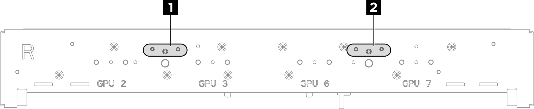
Tabela 1. Local de instalação do conjunto de suporte de serviço e placa fria da GPU Local de instalação Número do slot da GPU 1 GPU 2 e GPU 3 2 GPU 6 e GPU 7
- Limpe imediatamente o PCM e os protetores putty da GPU com panos de limpeza com álcool. Limpe cuidadosamente o PCM e os protetores putty para evitar danos à GPU.Atenção
Recomenda-se limpar o PCM enquanto ele está no estado líquido.
Os componentes elétricos ao redor do molde nas GPUs são extremamente delicados. Ao remover o molde o PCM e limpar o molde da GPU, evite tocar nos componentes elétricos para evitar danos.
Figura 8. Limpando o PCM e os protetores putty da GPU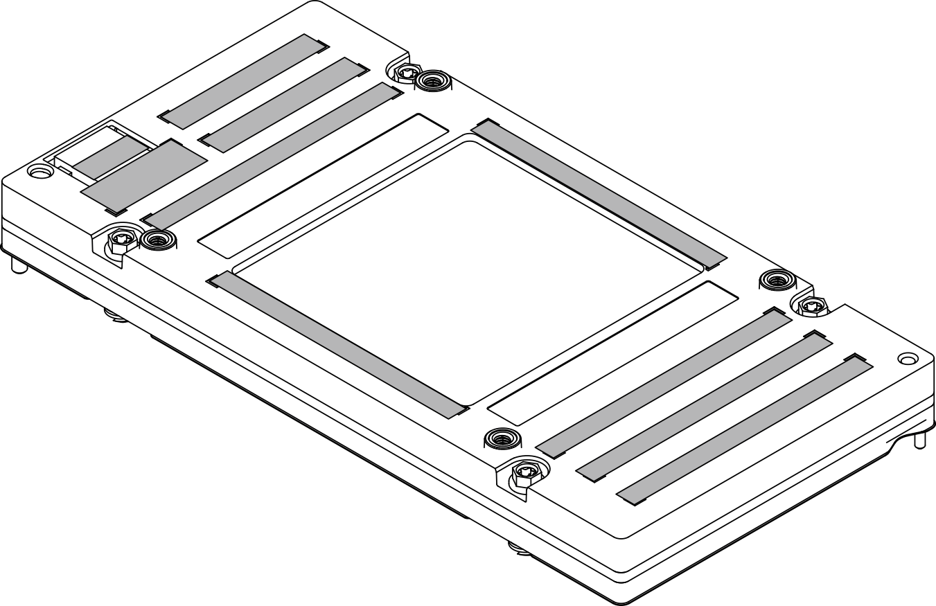
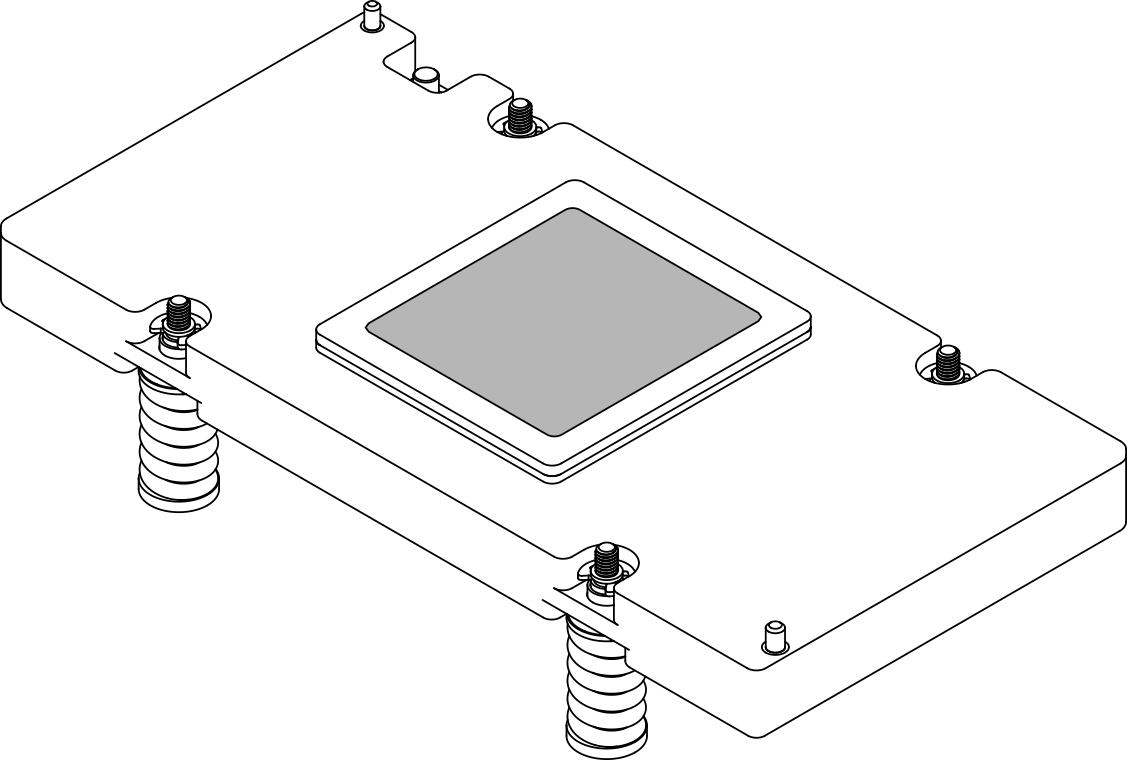
- Com panos de limpeza com álcool, limpe o protetor putty e os PCMs restantes da placa fria da GPU.Figura 9. Removendo o PCM e os protetores putty da placa fria
- Remova a GPU. Conecte os dois bits de extensão Torx T15 de 200 mm a duas chaves de fenda de torque. Solte simultaneamente os dois parafusos Torx T15 diagonais com a chave de fenda ajustada para o torque adequado.
- Ajuste a chave de fenda de torque para 0,6 Newton-metro, 5,3 libras-polegada para soltar simultaneamente os dois parafusos diagonais ; em seguida, solte simultaneamente os dois parafusos diagonais .Figura 10. Removendo a GPU

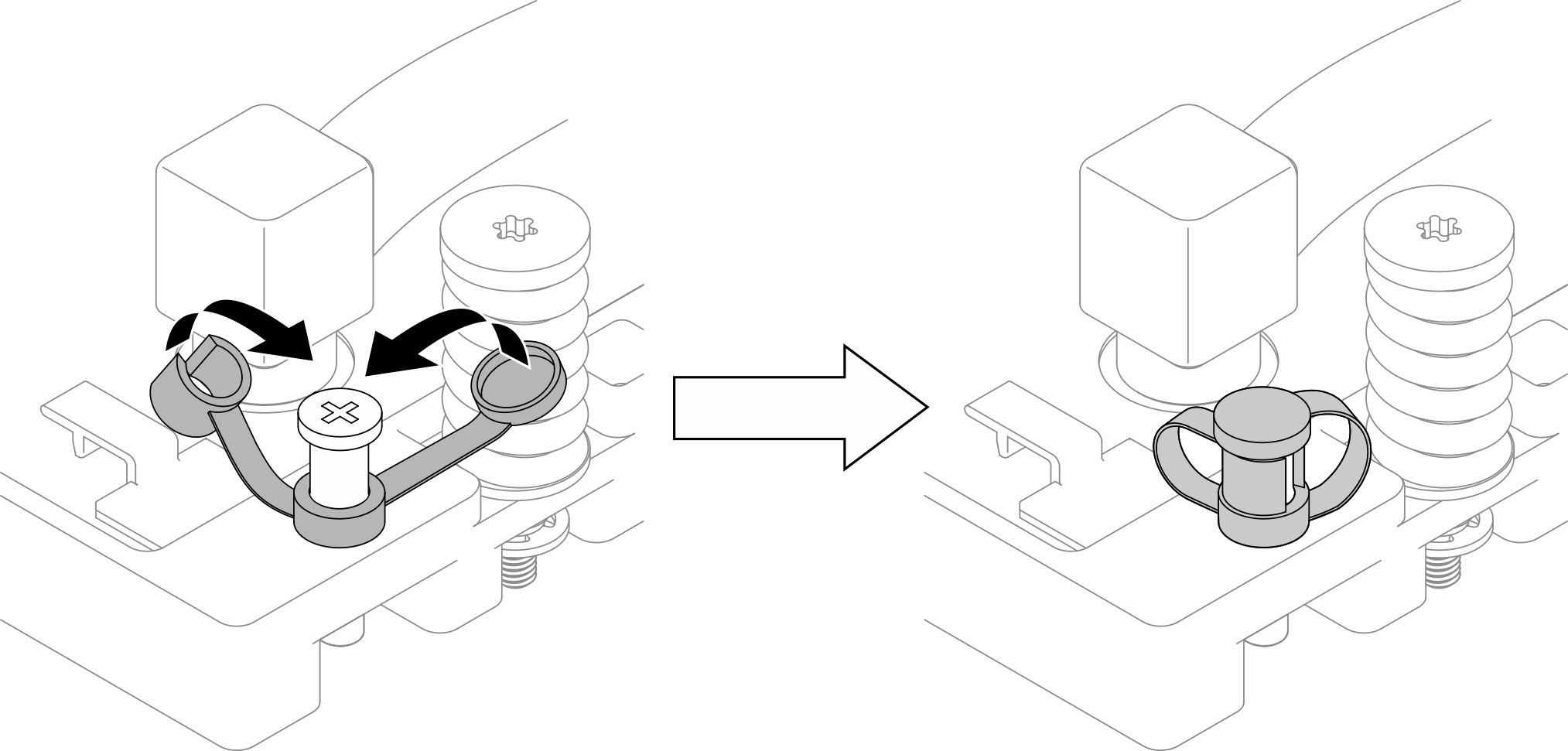
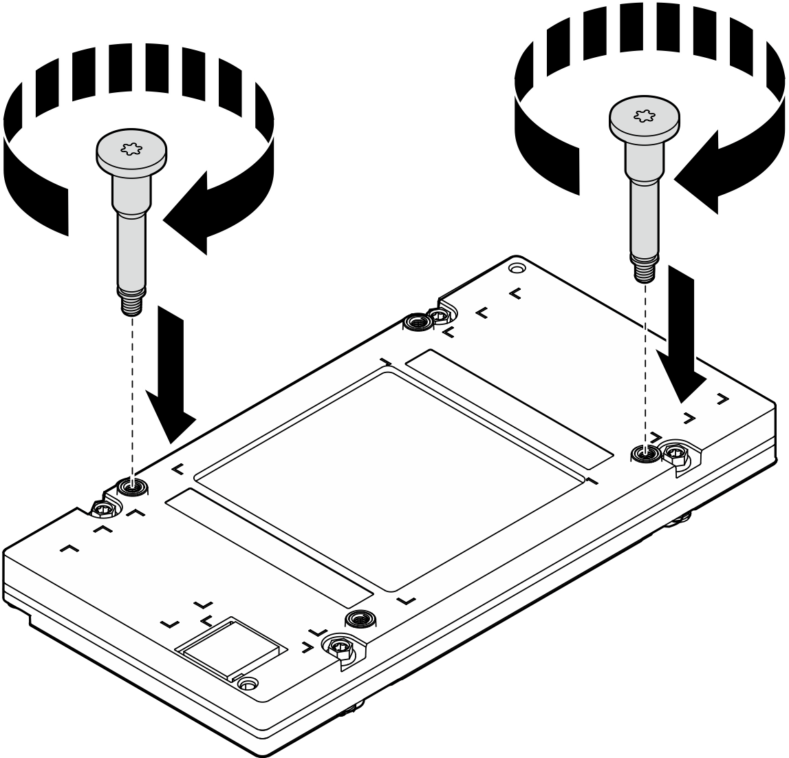
- Instale as duas alças com rosca da GPU na diagonal. Alinhe as alças dos parafusos aos slots dos parafusos da placa fria; em seguida, aperte as alças dos parafusos com a mão.Figura 11. Instalando as alças com rosca da GPU
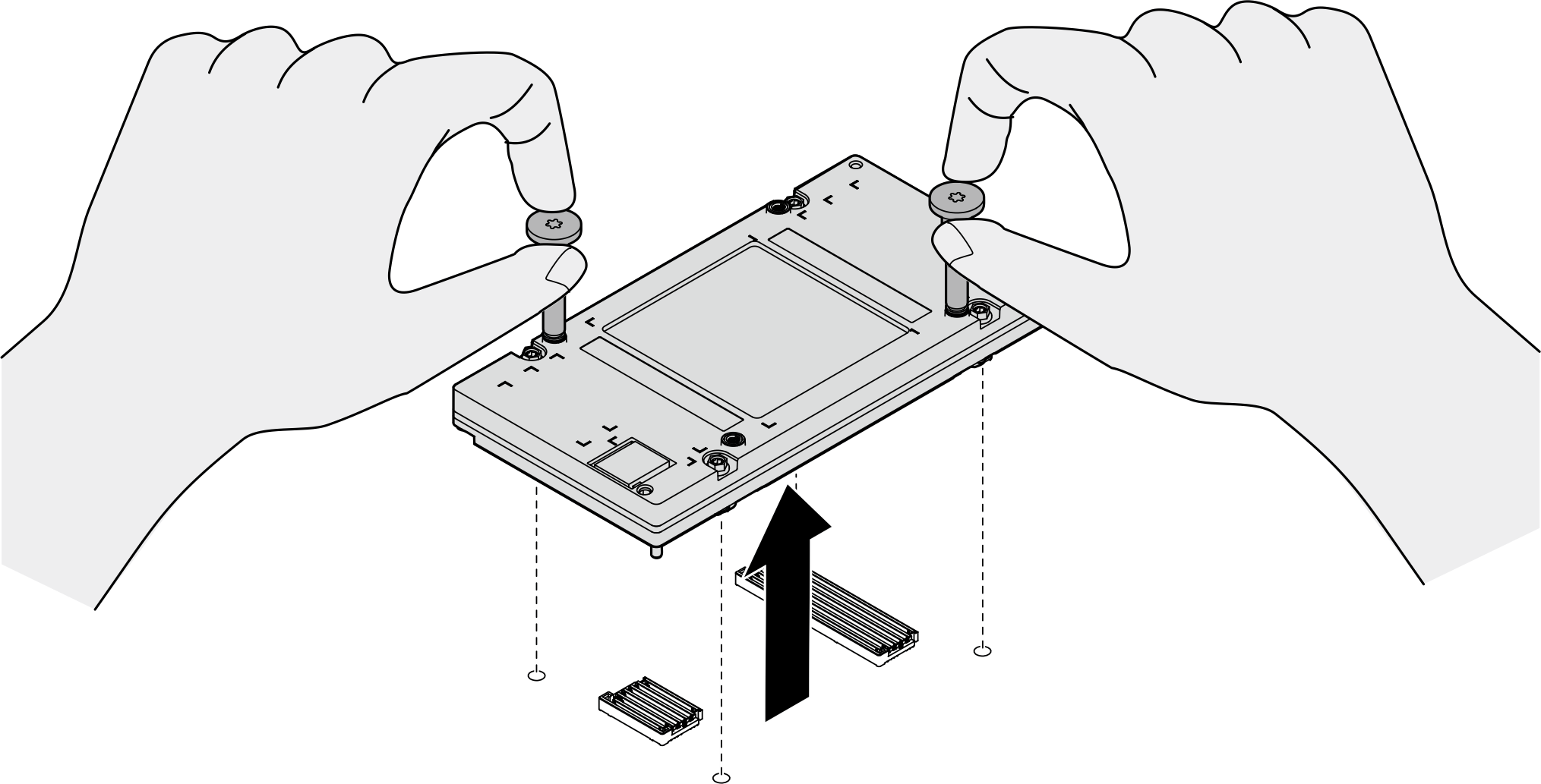
- Segure as alças dos parafusos da GPU para remover a GPU da respectiva placa-base.Figura 12. Removendo a GPU
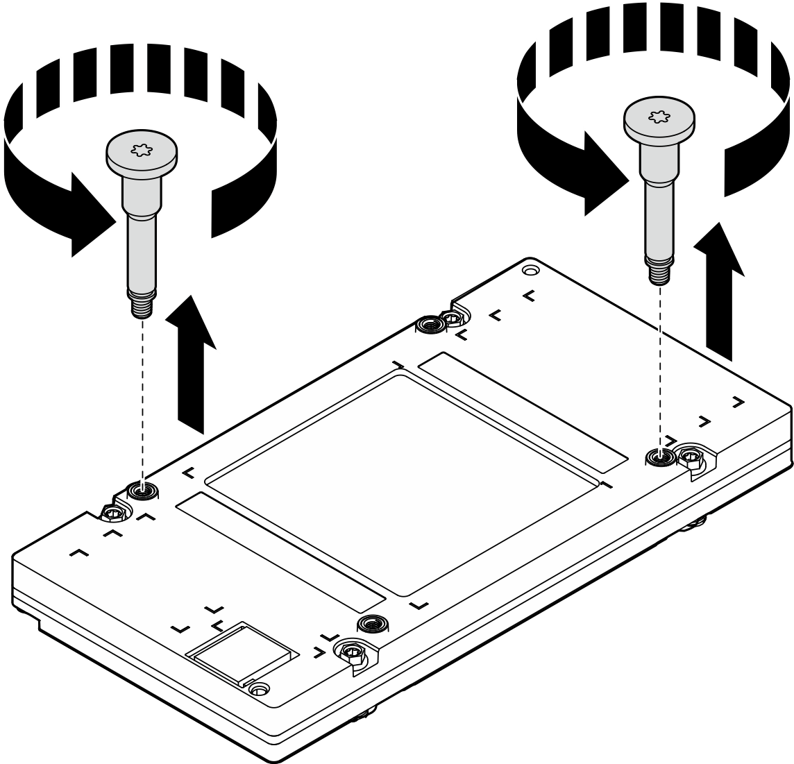
- Cuidadosamente, coloque a GPU em uma superfície protetora plana e estática. Remova as duas alças com rosca soltando-as com as mãos.Figura 13. Removendo as alças com rosca da GPU
- Ajuste a chave de fenda de torque para 0,6 Newton-metro, 5,3 libras-polegada para soltar simultaneamente os dois parafusos diagonais
Depois de concluir
- Instale uma unidade de substituição. Consulte Instalar uma GPU B200 traseira.
- Se você receber instruções para retornar o componente ou o dispositivo opcional, siga todas as instruções do pacote e use os materiais do pacote para remessa que foram fornecidos.