Install the 4U PCIe expansion tray
Follow instructions in this section to install the 4U PCIe expansion tray.
About this task
Attention
Go over Installation Guidelines to ensure that you work safely.
Touch the static-protective package that contains the component to any unpainted metal surface on the server; then, remove it from the package and place it on a static-protective surface.
Procedure
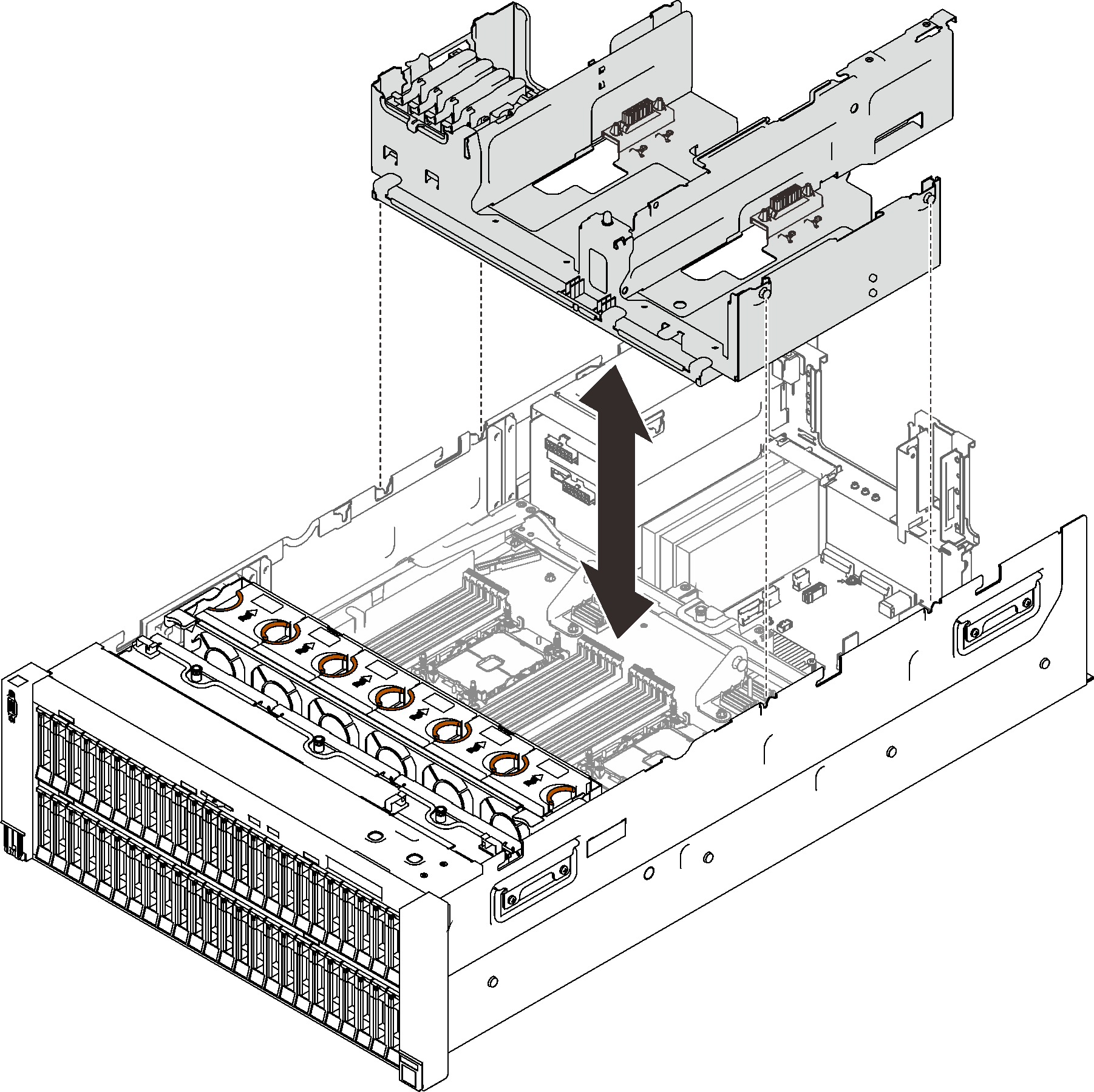
- Aligned the nailheads with the slots on both sides of the server, and lower the tray into the server.Figure 1. Installing the 4U PCIe expansion tray
- Connect both 4U PCIe riser power cables to the power backplane.Figure 2. Connecting 4U PCIe riser power cables
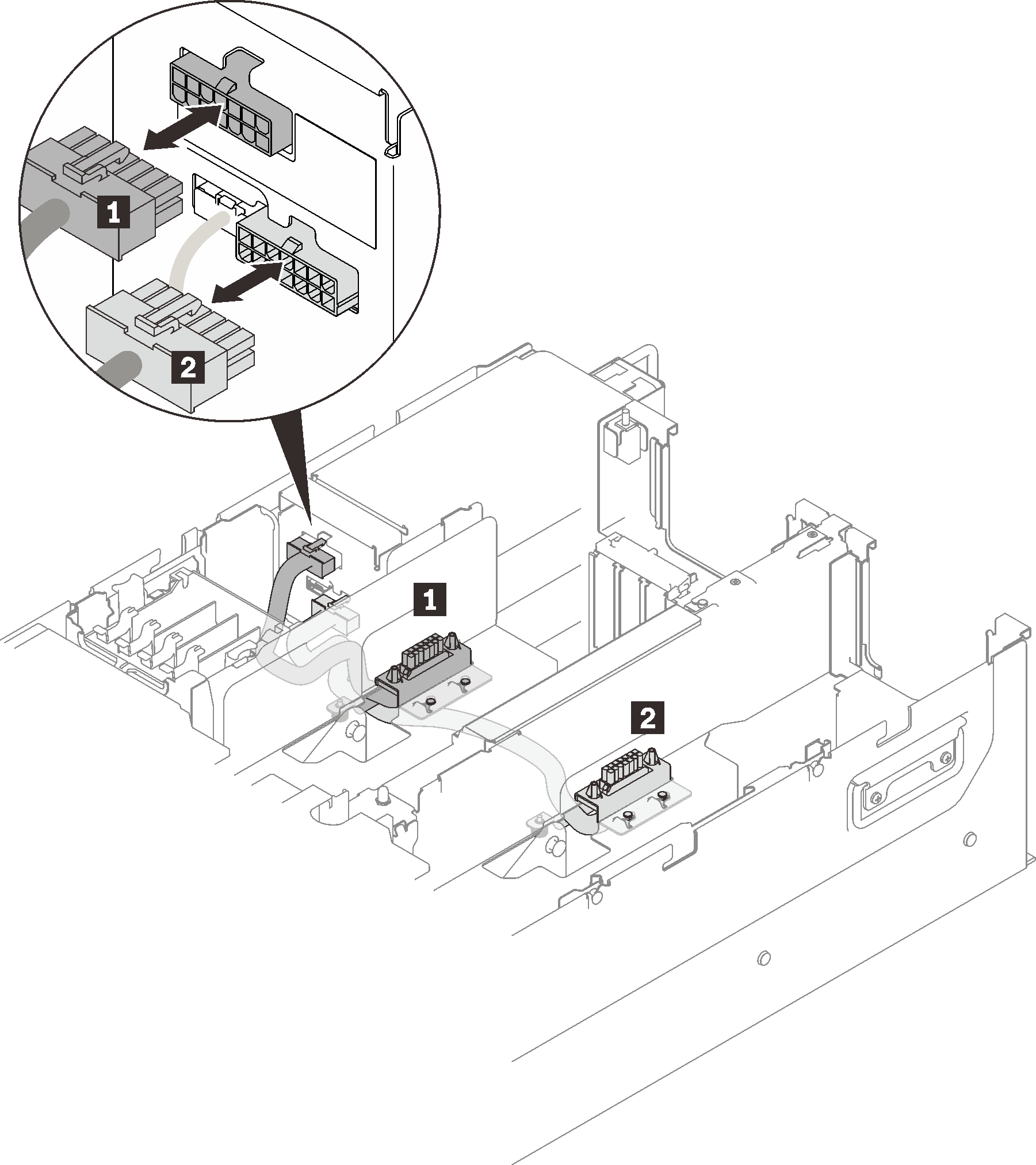
Table 1. 4U PCIe riser power cables Length From To 1 230 mm (shorter) PCIe riser cage 2 upper power connector 2 320 mm (longer) PCIe riser cage 1 lower power connector
After this task is completed
If applicable, connect M.2 or 7mm drive cables to the system board.
Figure 3. 7mm drive cage cable routing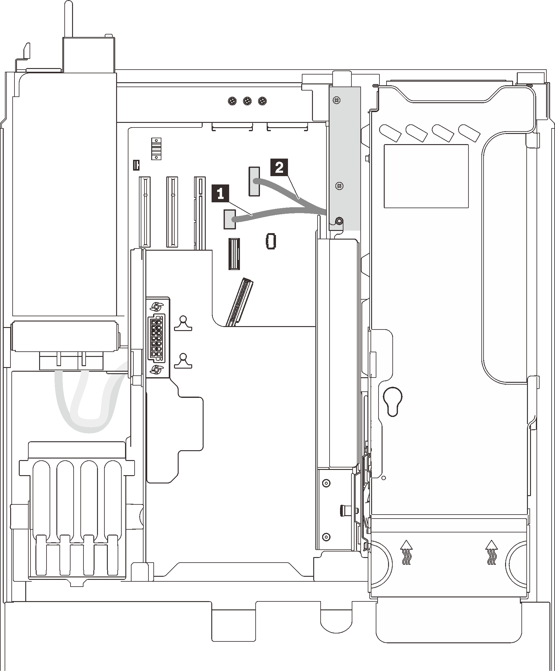 Figure 4. M.2 cable routing
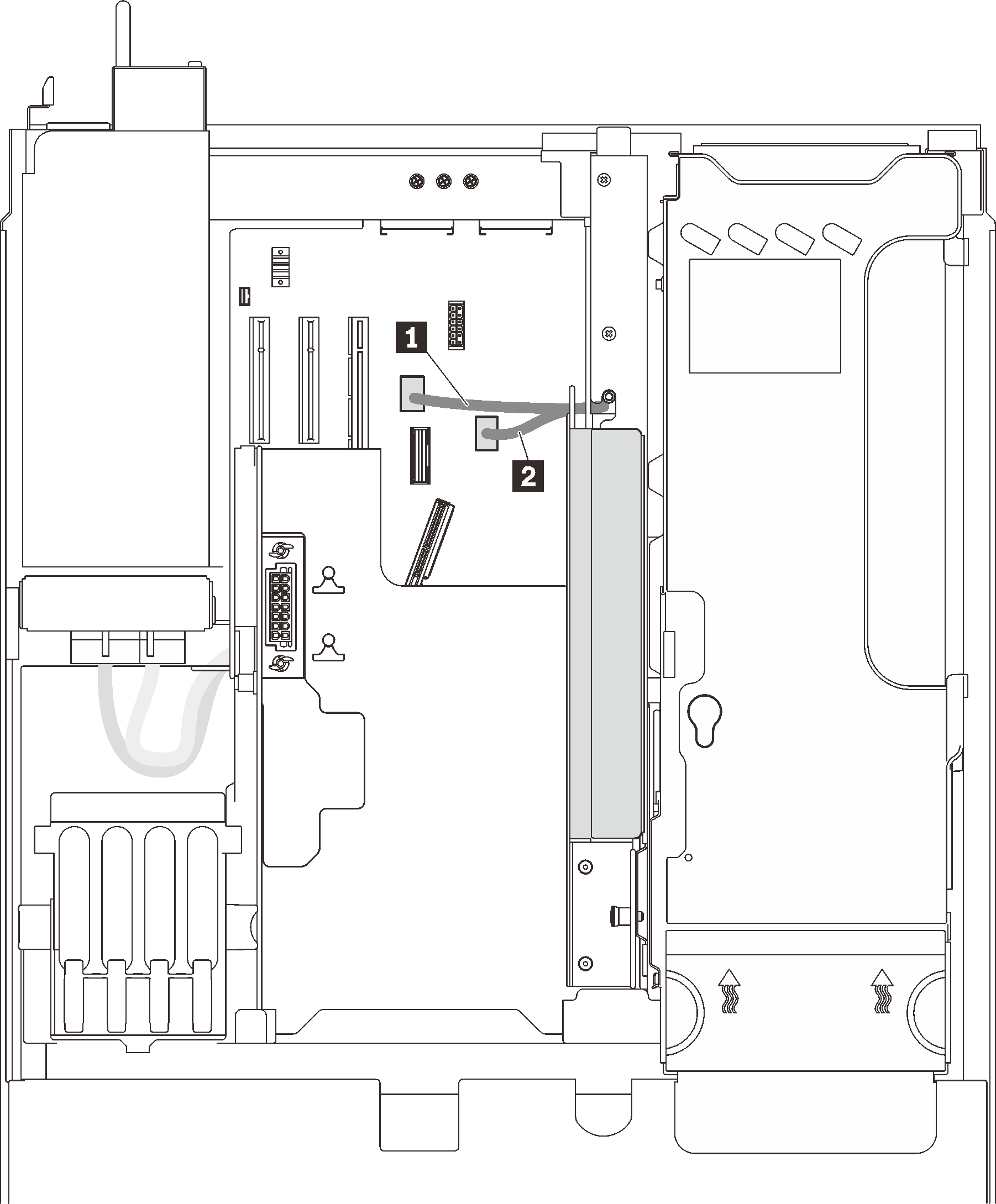
1 7mm drive signal connector 1 M.2 drive signal connector 2 7mm drive power connector 2 M.2 backplane power connector If applicable, connect all the flash power module cables.
Figure 5. Connecting flash power module cables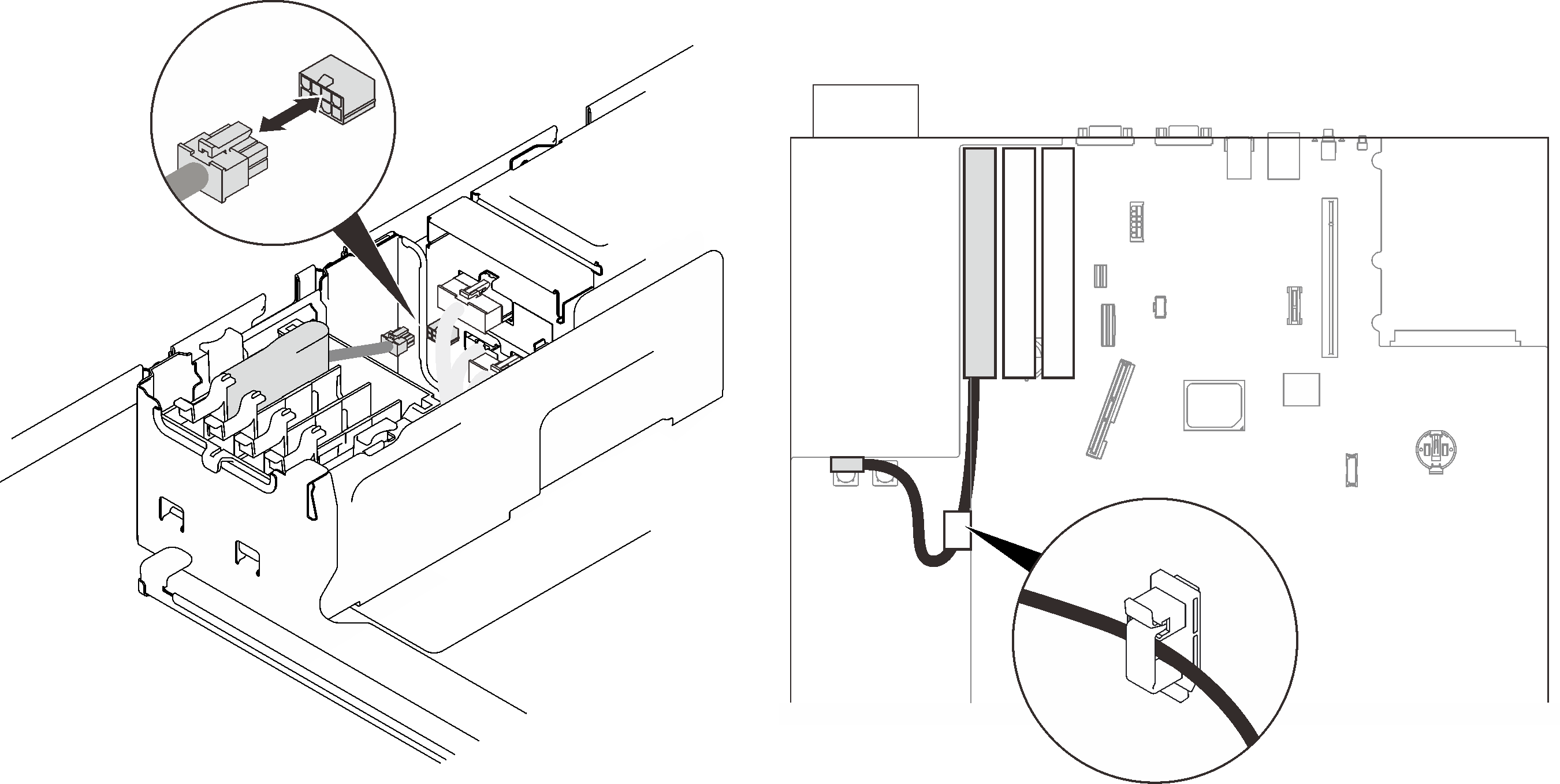
Proceed to complete the parts replacement (see Complete the parts replacement).
Demo video
Give documentation feedback