Install the 4U PCIe riser power cable assembly
Follow instructions in this section to install the 4U PCIe riser power cable assembly.
About this task
Attention
Go over Installation Guidelines to ensure that you work safely.
Touch the static-protective package that contains the component to any unpainted metal surface on the server; then, remove it from the package and place it on a static-protective surface.
Procedure
- Make sure the power cable is of the appropriate length for the slot.Figure 1. 4U PCIe riser power cables
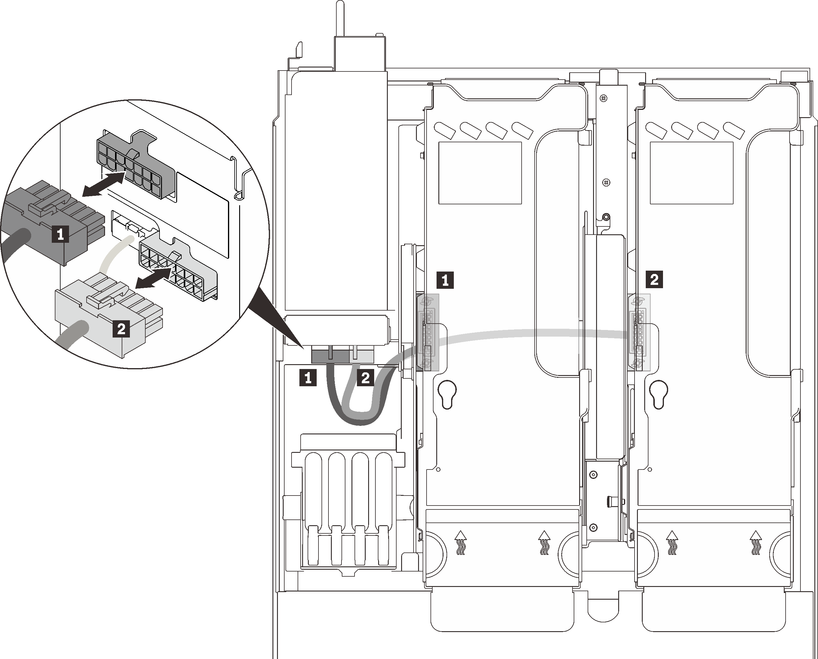
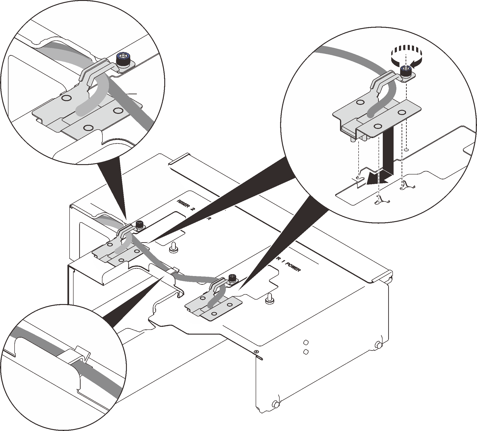
Table 1. 4U PCIe riser power cables Length From To 1 230 mm (shorter) PCIe riser cage 2 upper power connector 2 320 mm (longer) PCIe riser cage 1 lower power connector - Align the power cable assembly with the key-shaped slots on the bottom of the 4U PCIe expansion tray, and slide it backward to secure it.Figure 2. Installing the 4U PCIe riser power cable assemblies
After this task is completed
Proceed to complete the parts replacement (see Complete the parts replacement).
Demo video
Give documentation feedback