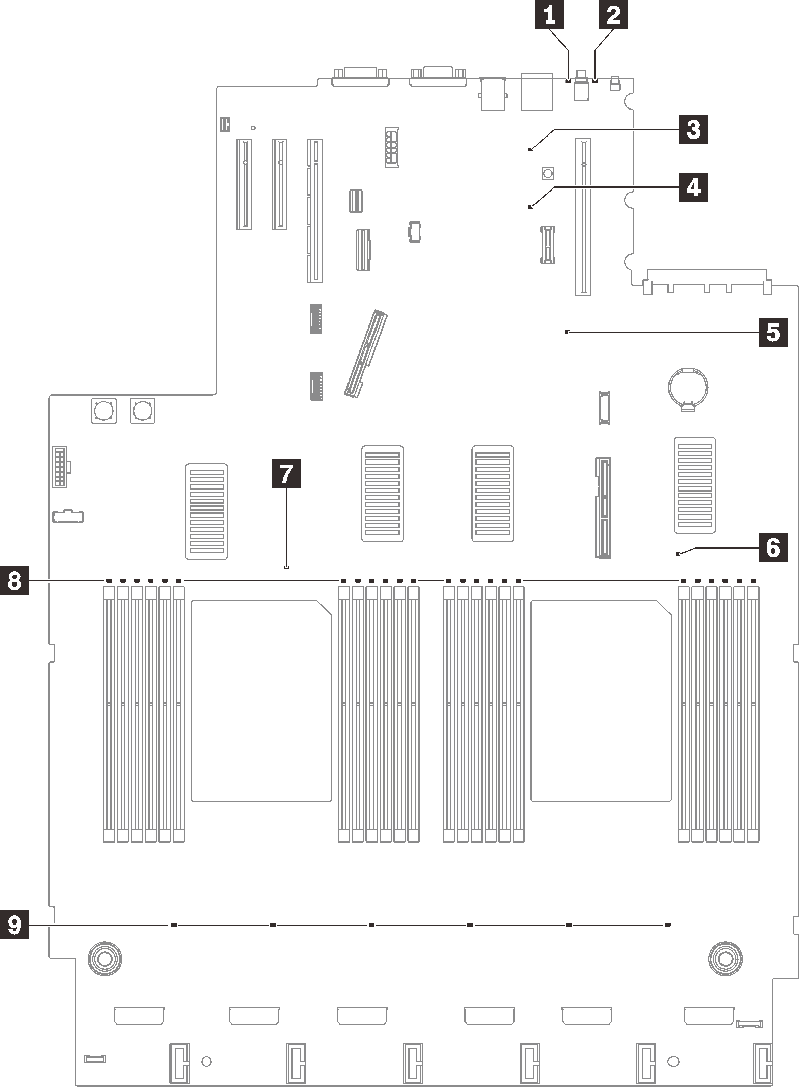
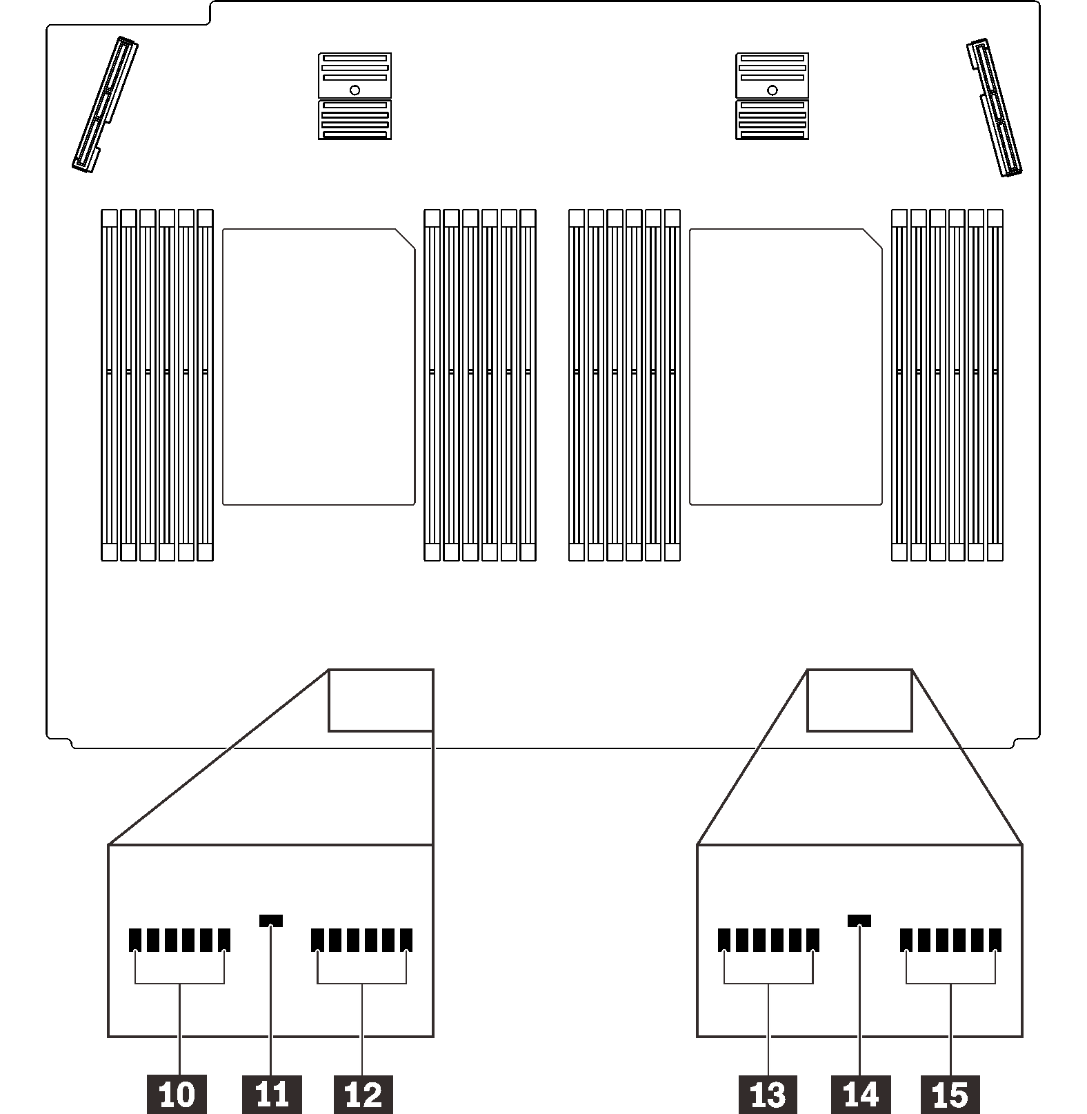
System board LEDs
The following illustrations show the light emitting diodes (LEDs) on the system board.
Figure 1. System board and expansion board LEDs
| LED | Descriptions and actions |
|---|---|
| 1 System error LED (yellow) | LED on: An error has occurred. Complete the following steps: |
| 2 Identification LED (blue) | This LED is used as a presence detection LED. You can use Lenovo XClarity Controller to light this LED remotely. Use this LED to locate the server among other servers visually. |
| 3 Light path power LED | This LED indicates if there is sufficient power to lit the LEDs when light path button is pressed while the system is not connected to the power. |
| 4 XCC heartbeat LED (green) | This LED indicates XCC heartbeat and boot process:
|
| 5 FPGA heartbeat LED (green) | This LED indicates power-on and power-off sequencing. |
| 6 7 11 14 Processor error LEDs | LED on: An error has occurred to the processor the LED represents. See Processor problems for more information. |
| 8 10 12 13 15 DIMM error LEDs | LED on: An error has occurred to the DIMM which the LED represents. See Memory problems for more information. |
| 9 Fan error LEDs | LED on: An error has occurred to the fan the LED represents. See Fan problems for more information. |
Give documentation feedback