방열판 및 팬 모듈의 케이블 배선
이 섹션의 지침에 따라 방열판 및 팬 모듈의 케이블 배선 방법을 알아보십시오.
그림 1. 95W 미만의 TDP가 장착된 프로세서용 방열판 및 팬 모듈의 케이블 배선
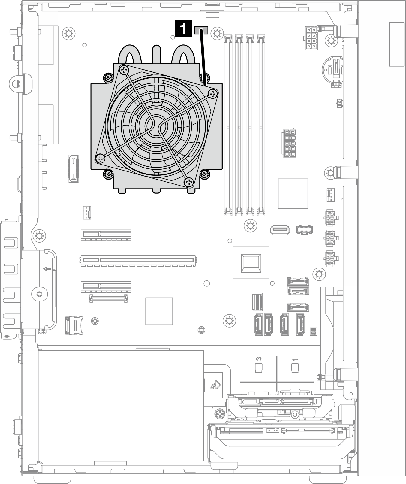
그림 2. 95W TDP가 장착된 프로세서용 방열판 및 팬 모듈의 케이블 배선
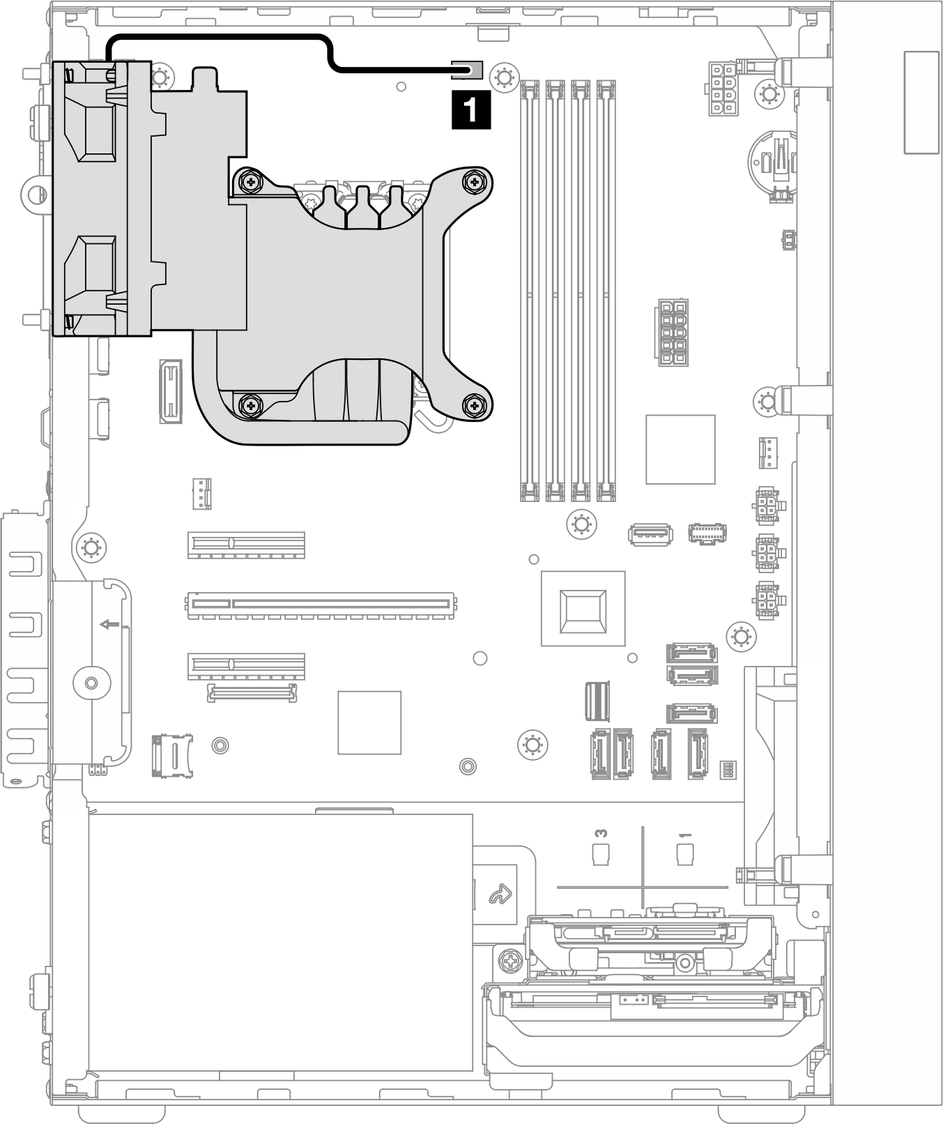
| 에서 | 끝 |
|---|---|
| 1 방열판 및 팬 모듈 케이블 | 시스템 보드의 프로세서 팬 커넥터 |
시스템 보드 커넥터 위치에 대해서는 케이블 배선용 시스템 보드 커넥터의 내용을 참조하십시오.
피드백 보내기