1 x SAS/SATA- + 2 x NVMe-Rückwandplatinen
In diesem Abschnitt sind die erforderlichen Komponenten für Servermodelle mit Rückwandplatinen für 1 x SAS/SATA- + 2 x NVMe-2,5-Zoll-Hot-Swap-Einheiten aufgeführt.
Verbindungen zwischen Anschlüssen: 1↔1, 2↔2, 3↔3, … n↔n
Stellen Sie beim Verlegen der Kabel sicher, dass alle Kabel ordnungsgemäß durch die Kabelführungen und Kabelklemmen geführt werden.
Y-Kabel werden in den Abbildungen für jede Rückwandplatine als einzelne Kabel dargestellt.
Schließen Sie die Kabel beginnend mit den GEN 4 RAID-Adaptern an.
Weitere Informationen zu den verwendeten Kabeln finden Sie unter Kabelliste für Rückwandplatine.
Onboard NVMe/SATA + 2 x Retimer
| NVMe-Kabelführung | ||
|---|---|---|
Anmerkung Je nach Konfiguration wird der Adapter im oberen oder im unteren PCIe-Bereich installiert. Abbildung 1. NVMe-Kabelführung zur Systemplatine und zum oberen PCIe-Bereich 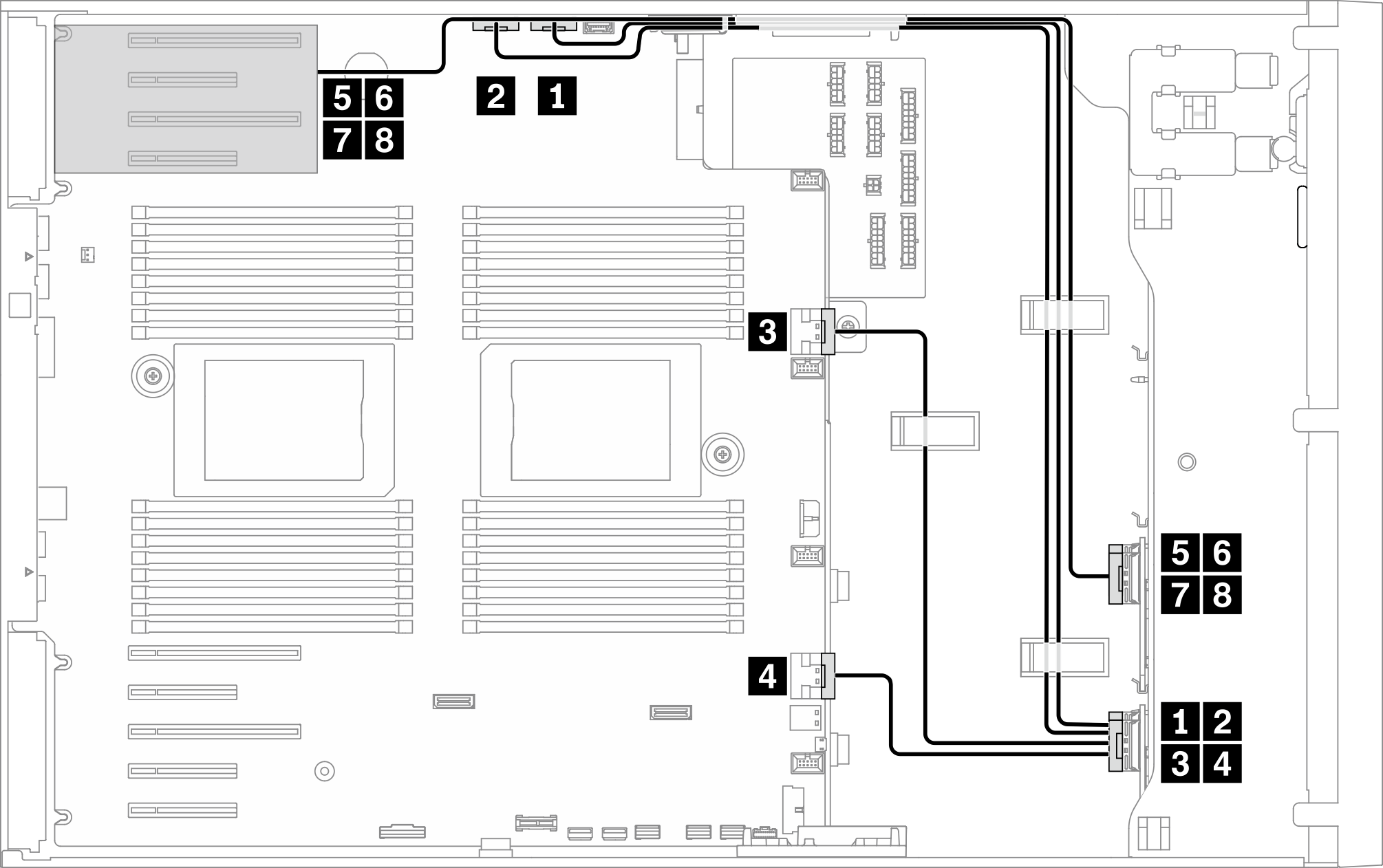 Abbildung 2. NVMe-Kabelführung zur Systemplatine und zum unteren PCIe-Bereich 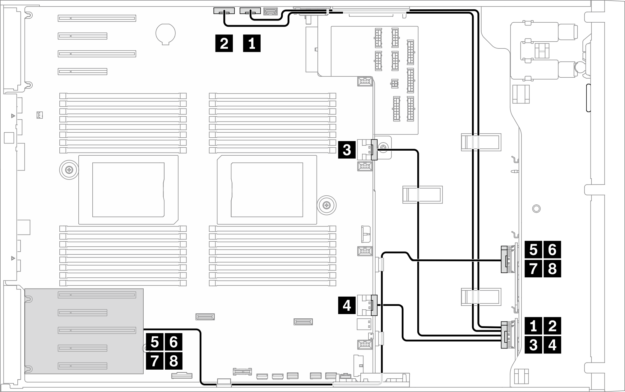 | ||
| Von | Zu | Kabel |
| 1 BP1: NVMe 0-1 | PCIe 1 (integriert) | SlimSAS x8 zu SlimSAS x8 Paar (820 mm/780 mm) |
| 2 BP1: NVMe 2-3 | PCIe 2 (integriert) | |
| 3 BP1: NVMe 4-5 | PCIe 3 (integriert) | SlimSAS x8 zu SlimSAS x8 Paar (325 mm/160 mm) |
| 4 BP1: NVMe 6-7 | PCIe 4 (integriert) | |
| 5 BP2: NVMe 0-1 | Retimer: C0 | SlimSAS x8 zu SlimSAS x8 Paar (700 mm/700 mm) |
| 6 BP2: NVMe 2-3 | Retimer: C1 | |
| 7 BP2: NVMe 4-5 | Retimer: C0 | SlimSAS x8 zu SlimSAS x8 Paar (700 mm/700 mm) |
| 8 BP2: NVMe 6-7 | Retimer: C1 | |
| SAS/SATA-Kabelführung | ||
|---|---|---|
Abbildung 3. SAS/SATA-Kabelführung zur Systemplatine 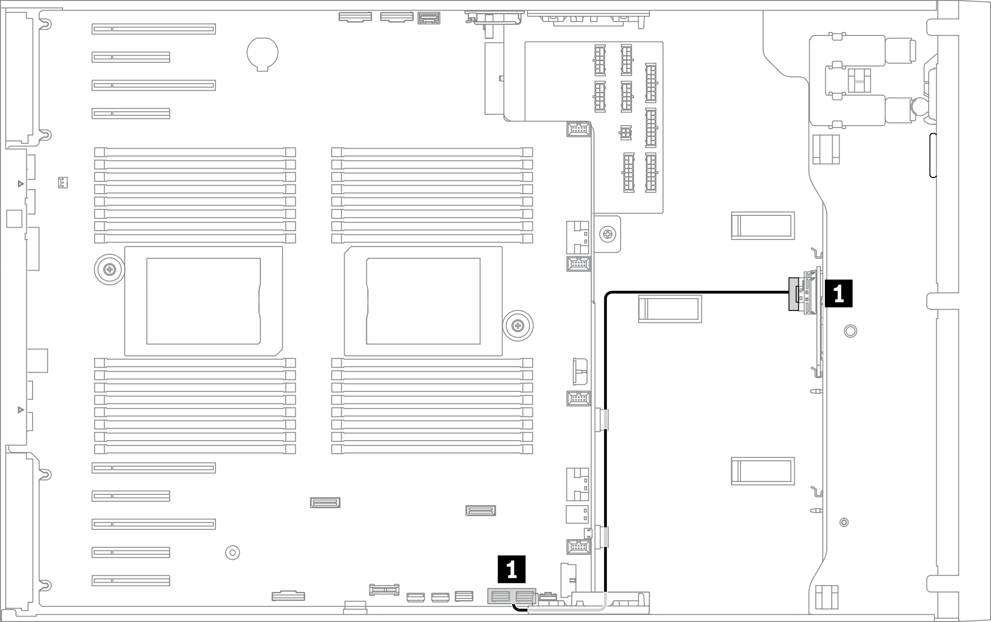 | ||
| Von | Zu | Kabel |
| 1 BP3: SAS/SATA | SATA 0-3, 4-7 (integriert) | SlimSAS x4*2 zu SlimSAS x8 (430 mm/430 mm) |
Onboard NVMe + 2 x Retimer + 1 x 8i RAID/HBA
| NVMe-Kabelführung | ||
|---|---|---|
Anmerkung Je nach Konfiguration wird der Adapter im oberen oder im unteren PCIe-Bereich installiert. Abbildung 4. NVMe-Kabelführung zur Systemplatine und zum oberen PCIe-Bereich Abbildung 5. NVMe-Kabelführung zur Systemplatine und zum unteren PCIe-Bereich | ||
| Von | Zu | Kabel |
| 1 BP1: NVMe 0-1 | PCIe 1 (integriert) | SlimSAS x8 zu SlimSAS x8 Paar (820 mm/780 mm) |
| 2 BP1: NVMe 2-3 | PCIe 2 (integriert) | |
| 3 BP1: NVMe 4-5 | PCIe 3 (integriert) | SlimSAS x8 zu SlimSAS x8 Paar (325 mm/160 mm) |
| 4 BP1: NVMe 6-7 | PCIe 4 (integriert) | |
| 5 BP2: NVMe 0-1 | Retimer: C0 | SlimSAS x8 zu SlimSAS x8 Paar (700 mm/700 mm) |
| 6 BP2: NVMe 2-3 | Retimer: C1 | |
| 7 BP2: NVMe 4-5 | Retimer: C0 | SlimSAS x8 zu SlimSAS x8 Paar (700 mm/700 mm) |
| 8 BP2: NVMe 6-7 | Retimer: C1 | |
| SAS/SATA-Kabelführung | ||
|---|---|---|
Abbildung 6. SAS/SATA-Kabelführung zu PCIe-Steckplatz 9 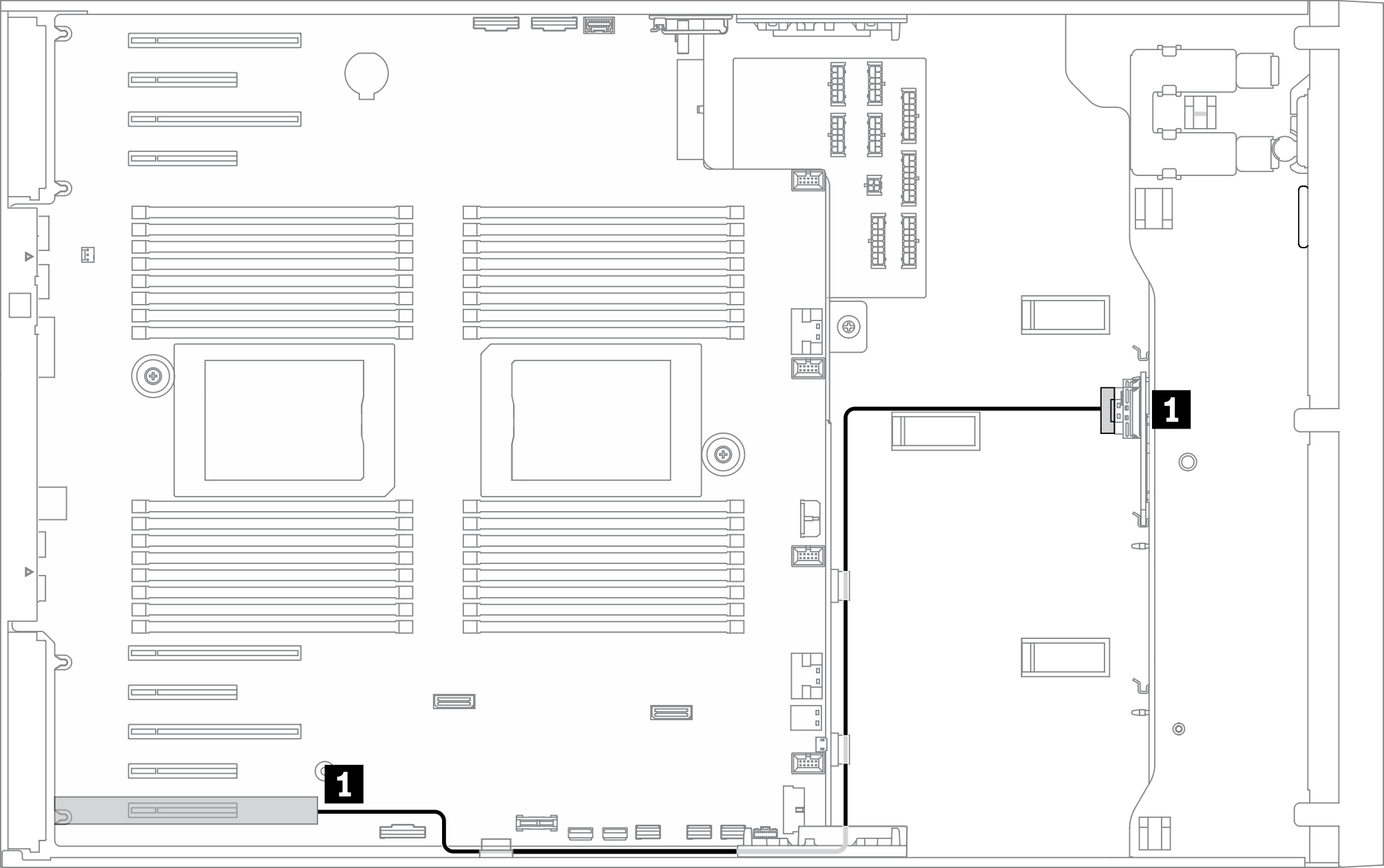 | ||
| Von | Zu | Kabel |
| 1 BP3: SAS/SATA |
|
|
Onboard NVMe + 2 x Retimer + 1 x 16i RAID/HBA
| NVMe-Kabelführung | ||
|---|---|---|
Anmerkung Je nach Konfiguration wird der Adapter im oberen oder im unteren PCIe-Bereich installiert. Abbildung 7. NVMe-Kabelführung zur Systemplatine und zum oberen PCIe-Bereich Abbildung 8. NVMe-Kabelführung zur Systemplatine und zum unteren PCIe-Bereich | ||
| Von | Zu | Kabel |
| 1 BP1: NVMe 0-1 | PCIe 1 (integriert) | SlimSAS x8 zu SlimSAS x8 Paar (820 mm/780 mm) |
| 2 BP1: NVMe 2-3 | PCIe 2 (integriert) | |
| 3 BP1: NVMe 4-5 | PCIe 3 (integriert) | SlimSAS x8 zu SlimSAS x8 Paar (325 mm/160 mm) |
| 4 BP1: NVMe 6-7 | PCIe 4 (integriert) | |
| 5 BP2: NVMe 0-1 | Retimer: C0 | SlimSAS x8 zu SlimSAS x8 Paar (700 mm/700 mm) |
| 6 BP2: NVMe 2-3 | Retimer: C1 | |
| 7 BP2: NVMe 4-5 | Retimer: C0 | SlimSAS x8 zu SlimSAS x8 Paar (700 mm/700 mm) |
| 8 BP2: NVMe 6-7 | Retimer: C1 | |
| SAS/SATA-Kabelführung | ||
|---|---|---|
Abbildung 9. SAS/SATA-Kabelführung zu PCIe-Steckplatz 9 | ||
| Von | Zu | Kabel |
| 1 BP3: SAS/SATA |
|
|
Onboard NVMe+ 2 x Retimer + 1 × 24i RAID/HBA
| NVMe-Kabelführung | ||
|---|---|---|
Anmerkung Je nach Konfiguration wird der Adapter im oberen oder im unteren PCIe-Bereich installiert. Abbildung 10. NVMe-Kabelführung zur Systemplatine und zum oberen PCIe-Bereich Abbildung 11. NVMe-Kabelführung zur Systemplatine und zum unteren PCIe-Bereich | ||
| Von | Zu | Kabel |
| 1 BP1: NVMe 0-1 | PCIe 1 (integriert) | SlimSAS x8 zu SlimSAS x8 Paar (820 mm/780 mm) |
| 2 BP1: NVMe 2-3 | PCIe 2 (integriert) | |
| 3 BP1: NVMe 4-5 | PCIe 3 (integriert) | SlimSAS x8 zu SlimSAS x8 Paar (325 mm/160 mm) |
| 4 BP1: NVMe 6-7 | PCIe 4 (integriert) | |
| 5 BP2: NVMe 0-1 | Retimer: C0 | SlimSAS x8 zu SlimSAS x8 Paar (700 mm/700 mm) |
| 6 BP2: NVMe 2-3 | Retimer: C1 | |
| 7 BP2: NVMe 4-5 | Retimer: C0 | SlimSAS x8 zu SlimSAS x8 Paar (700 mm/700 mm) |
| 8 BP2: NVMe 6-7 | Retimer: C1 | |
| SAS/SATA-Kabelführung | ||
|---|---|---|
Abbildung 12. SAS/SATA-Kabelführung zu PCIe-Steckplatz 9 | ||
| Von | Zu | Kabel |
| 1 BP3: SAS/SATA | 24i G3: C0, C1 | Gen 3: Mini-SAS x4*2 zu SlimSAS x8 (930 mm) |
Onboard NVMe + 2 x Retimer + 1 x 32i RAID/HBA
| NVMe-Kabelführung | ||
|---|---|---|
Anmerkung Je nach Konfiguration wird der Adapter im oberen oder im unteren PCIe-Bereich installiert. Abbildung 13. NVMe-Kabelführung zur Systemplatine und zum oberen PCIe-Bereich Abbildung 14. NVMe-Kabelführung zur Systemplatine und zum unteren PCIe-Bereich | ||
| Von | Zu | Kabel |
| 1 BP1: NVMe 0-1 | PCIe 1 (integriert) | SlimSAS x8 zu SlimSAS x8 Paar (820 mm/780 mm) |
| 2 BP1: NVMe 2-3 | PCIe 2 (integriert) | |
| 3 BP1: NVMe 4-5 | PCIe 3 (integriert) | SlimSAS x8 zu SlimSAS x8 Paar (325 mm/160 mm) |
| 4 BP1: NVMe 6-7 | PCIe 4 (integriert) | |
| 5 BP2: NVMe 0-1 | Retimer: C0 | SlimSAS x8 zu SlimSAS x8 Paar (700 mm/700 mm) |
| 6 BP2: NVMe 2-3 | Retimer: C1 | |
| 7 BP2: NVMe 4-5 | Retimer: C0 | SlimSAS x8 zu SlimSAS x8 Paar (700 mm/700 mm) |
| 8 BP2: NVMe 6-7 | Retimer: C1 | |
| SAS/SATA-Kabelführung | ||
|---|---|---|
Abbildung 15. SAS/SATA-Kabelführung zu PCIe-Steckplatz 9 | ||
| Von | Zu | Kabel |
| 1 BP3: SAS/SATA | 32i G4: C0 | SlimSAS x8 zu SlimSAS x8 (720 mm) |
Onboard SATA + 4 x Retimer
| NVMe-Kabelführung | ||
|---|---|---|
Anmerkung Je nach Konfiguration wird der Adapter im oberen oder im unteren PCIe-Bereich installiert. Abbildung 16. NVMe-Kabelführung zum oberen PCIe-Bereich 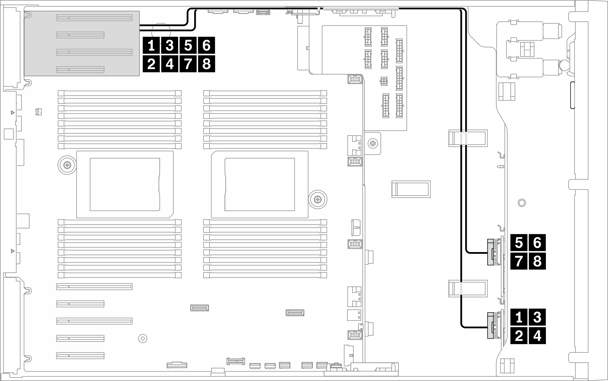 Abbildung 17. NVMe-Kabelführung zum unteren PCIe-Bereich 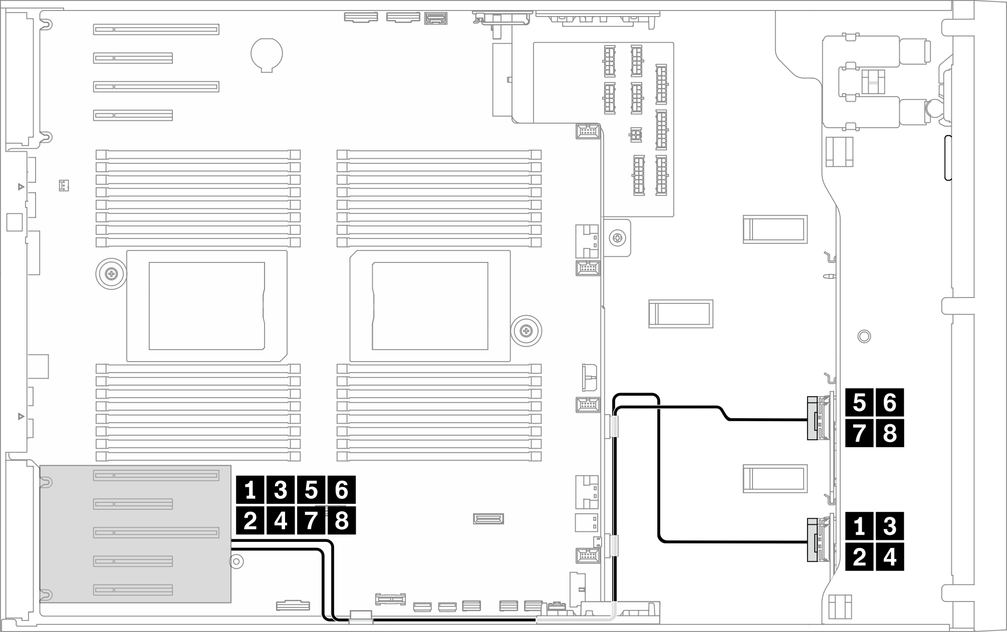 | ||
| Von | Zu | Kabel |
| 1 BP1: NVMe 0-1 | Retimer: C0 | SlimSAS x8 zu SlimSAS x8 Paar (700 mm/700 mm) |
| 2 BP1: NVMe 2-3 | Retimer: C1 | |
| 3 BP1: NVMe 4-5 | Retimer: C0 | SlimSAS x8 zu SlimSAS x8 Paar (700 mm/700 mm) |
| 4 BP1: NVMe 6-7 | Retimer: C1 | |
| 5 BP2: NVMe 0-1 | Retimer: C0 | SlimSAS x8 zu SlimSAS x8 Paar (700 mm/700 mm) |
| 6 BP2: NVMe 2-3 | Retimer: C1 | |
| 7 BP2: NVMe 4-5 | Retimer: C0 | SlimSAS x8 zu SlimSAS x8 Paar (700 mm/700 mm) |
| 8 BP2: NVMe 6-7 | Retimer: C1 | |
| SAS/SATA-Kabelführung | ||
|---|---|---|
Abbildung 18. SAS/SATA-Kabelführung zur Systemplatine | ||
| Von | Zu | Kabel |
| 1 BP3: SAS/SATA | SATA 0-3, 4-7 (integriert) | SlimSAS x4*2 zu SlimSAS x8 (430 mm/430 mm) |
4 x Retimer + 1 x 8i RAID/HBA
| NVMe-Kabelführung | ||
|---|---|---|
Anmerkung Je nach Konfiguration wird der Adapter im oberen oder im unteren PCIe-Bereich installiert. Abbildung 19. NVMe-Kabelführung zum oberen PCIe-Bereich Abbildung 20. NVMe-Kabelführung zum unteren PCIe-Bereich | ||
| Von | Zu | Kabel |
| 1 BP1: NVMe 0-1 | Retimer: C0 | SlimSAS x8 zu SlimSAS x8 Paar (700 mm/700 mm) |
| 2 BP1: NVMe 2-3 | Retimer: C1 | |
| 3 BP1: NVMe 4-5 | Retimer: C0 | SlimSAS x8 zu SlimSAS x8 Paar (700 mm/700 mm) |
| 4 BP1: NVMe 6-7 | Retimer: C1 | |
| 5 BP2: NVMe 0-1 | Retimer: C0 | SlimSAS x8 zu SlimSAS x8 Paar (700 mm/700 mm) |
| 6 BP2: NVMe 2-3 | Retimer: C1 | |
| 7 BP2: NVMe 4-5 | Retimer: C0 | SlimSAS x8 zu SlimSAS x8 Paar (700 mm/700 mm) |
| 8 BP2: NVMe 6-7 | Retimer: C1 | |
| SAS/SATA-Kabelführung | ||
|---|---|---|
Abbildung 21. SAS/SATA-Kabelführung zu PCIe-Steckplatz 9 | ||
| Von | Zu | Kabel |
| 1 BP3: SAS/SATA |
|
|
4 x Retimer + 1 x 16i RAID/HBA
| NVMe-Kabelführung | ||
|---|---|---|
Anmerkung Je nach Konfiguration wird der Adapter im oberen oder im unteren PCIe-Bereich installiert. Abbildung 22. NVMe-Kabelführung zum oberen PCIe-Bereich Abbildung 23. NVMe-Kabelführung zum unteren PCIe-Bereich | ||
| Von | Zu | Kabel |
| 1 BP1: NVMe 0-1 | Retimer: C0 | SlimSAS x8 zu SlimSAS x8 Paar (700 mm/700 mm) |
| 2 BP1: NVMe 2-3 | Retimer: C1 | |
| 3 BP1: NVMe 4-5 | Retimer: C0 | SlimSAS x8 zu SlimSAS x8 Paar (700 mm/700 mm) |
| 4 BP1: NVMe 6-7 | Retimer: C1 | |
| 5 BP2: NVMe 0-1 | Retimer: C0 | SlimSAS x8 zu SlimSAS x8 Paar (700 mm/700 mm) |
| 6 BP2: NVMe 2-3 | Retimer: C1 | |
| 7 BP2: NVMe 4-5 | Retimer: C0 | SlimSAS x8 zu SlimSAS x8 Paar (700 mm/700 mm) |
| 8 BP2: NVMe 6-7 | Retimer: C1 | |
| SAS/SATA-Kabelführung | ||
|---|---|---|
Abbildung 24. SAS/SATA-Kabelführung zu PCIe-Steckplatz 9 | ||
| Von | Zu | Kabel |
| 1 BP3: SAS/SATA |
|
|
4 x Retimer + 1 x 24i RAID/HBA
| NVMe-Kabelführung | ||
|---|---|---|
Anmerkung Je nach Konfiguration wird der Adapter im oberen oder im unteren PCIe-Bereich installiert. Abbildung 25. NVMe-Kabelführung zum oberen PCIe-Bereich Abbildung 26. NVMe-Kabelführung zum unteren PCIe-Bereich | ||
| Von | Zu | Kabel |
| 1 BP1: NVMe 0-1 | Retimer: C0 | SlimSAS x8 zu SlimSAS x8 Paar (700 mm/700 mm) |
| 2 BP1: NVMe 2-3 | Retimer: C1 | |
| 3 BP1: NVMe 4-5 | Retimer: C0 | SlimSAS x8 zu SlimSAS x8 Paar (700 mm/700 mm) |
| 4 BP1: NVMe 6-7 | Retimer: C1 | |
| 5 BP2: NVMe 0-1 | Retimer: C0 | SlimSAS x8 zu SlimSAS x8 Paar (700 mm/700 mm) |
| 6 BP2: NVMe 2-3 | Retimer: C1 | |
| 7 BP2: NVMe 4-5 | Retimer: C0 | SlimSAS x8 zu SlimSAS x8 Paar (700 mm/700 mm) |
| 8 BP2: NVMe 6-7 | Retimer: C1 | |
| SAS/SATA-Kabelführung | ||
|---|---|---|
Abbildung 27. SAS/SATA-Kabelführung zu PCIe-Steckplatz 9 | ||
| Von | Zu | Kabel |
| 1 BP3: SAS/SATA | 24i G3: C0, C1 | Gen 3: Mini-SAS x4*2 zu SlimSAS x8 (930 mm) |
4 x Retimer + 1 x 32i RAID/HBA
| NVMe-Kabelführung | ||
|---|---|---|
Anmerkung Je nach Konfiguration wird der Adapter im oberen oder im unteren PCIe-Bereich installiert. Abbildung 28. NVMe-Kabelführung zum oberen PCIe-Bereich Abbildung 29. NVMe-Kabelführung zum unteren PCIe-Bereich | ||
| Von | Zu | Kabel |
| 1 BP1: NVMe 0-1 | Retimer: C0 | SlimSAS x8 zu SlimSAS x8 Paar (700 mm/700 mm) |
| 2 BP1: NVMe 2-3 | Retimer: C1 | |
| 3 BP1: NVMe 4-5 | Retimer: C0 | SlimSAS x8 zu SlimSAS x8 Paar (700 mm/700 mm) |
| 4 BP1: NVMe 6-7 | Retimer: C1 | |
| 5 BP2: NVMe 0-1 | Retimer: C0 | SlimSAS x8 zu SlimSAS x8 Paar (700 mm/700 mm) |
| 6 BP2: NVMe 2-3 | Retimer: C1 | |
| 7 BP2: NVMe 4-5 | Retimer: C0 | SlimSAS x8 zu SlimSAS x8 Paar (700 mm/700 mm) |
| 8 BP2: NVMe 6-7 | Retimer: C1 | |
| SAS/SATA-Kabelführung | ||
|---|---|---|
Abbildung 30. SAS/SATA-Kabelführung zu PCIe-Steckplatz 9 | ||
| Von | Zu | Kabel |
| 1 BP3: SAS/SATA | 32i G4: C0 | SlimSAS x8 zu SlimSAS x8 (720 mm) |
4 x Retimer + 1 x CFF RAID/HBA
| NVMe-Kabelführung | ||
|---|---|---|
Anmerkung Je nach Konfiguration wird der Adapter im oberen oder im unteren PCIe-Bereich installiert. Abbildung 31. NVMe-Kabelführung zum oberen PCIe-Bereich Abbildung 32. NVMe-Kabelführung zum unteren PCIe-Bereich | ||
| Von | Zu | Kabel |
| 1 BP1: NVMe 0-1 | Retimer: C0 | SlimSAS x8 zu SlimSAS x8 Paar (700 mm/700 mm) |
| 2 BP1: NVMe 2-3 | Retimer: C1 | |
| 3 BP1: NVMe 4-5 | Retimer: C0 | SlimSAS x8 zu SlimSAS x8 Paar (700 mm/700 mm) |
| 4 BP1: NVMe 6-7 | Retimer: C1 | |
| 5 BP2: NVMe 0-1 | Retimer: C0 | SlimSAS x8 zu SlimSAS x8 Paar (700 mm/700 mm) |
| 6 BP2: NVMe 2-3 | Retimer: C1 | |
| 7 BP2: NVMe 4-5 | Retimer: C0 | SlimSAS x8 zu SlimSAS x8 Paar (700 mm/700 mm) |
| 8 BP2: NVMe 6-7 | Retimer: C1 | |
| SAS/SATA-Kabelführung | ||
|---|---|---|
Abbildung 33. SAS/SATA-Kabelführung zum CFF RAID-/HBA-Adapter 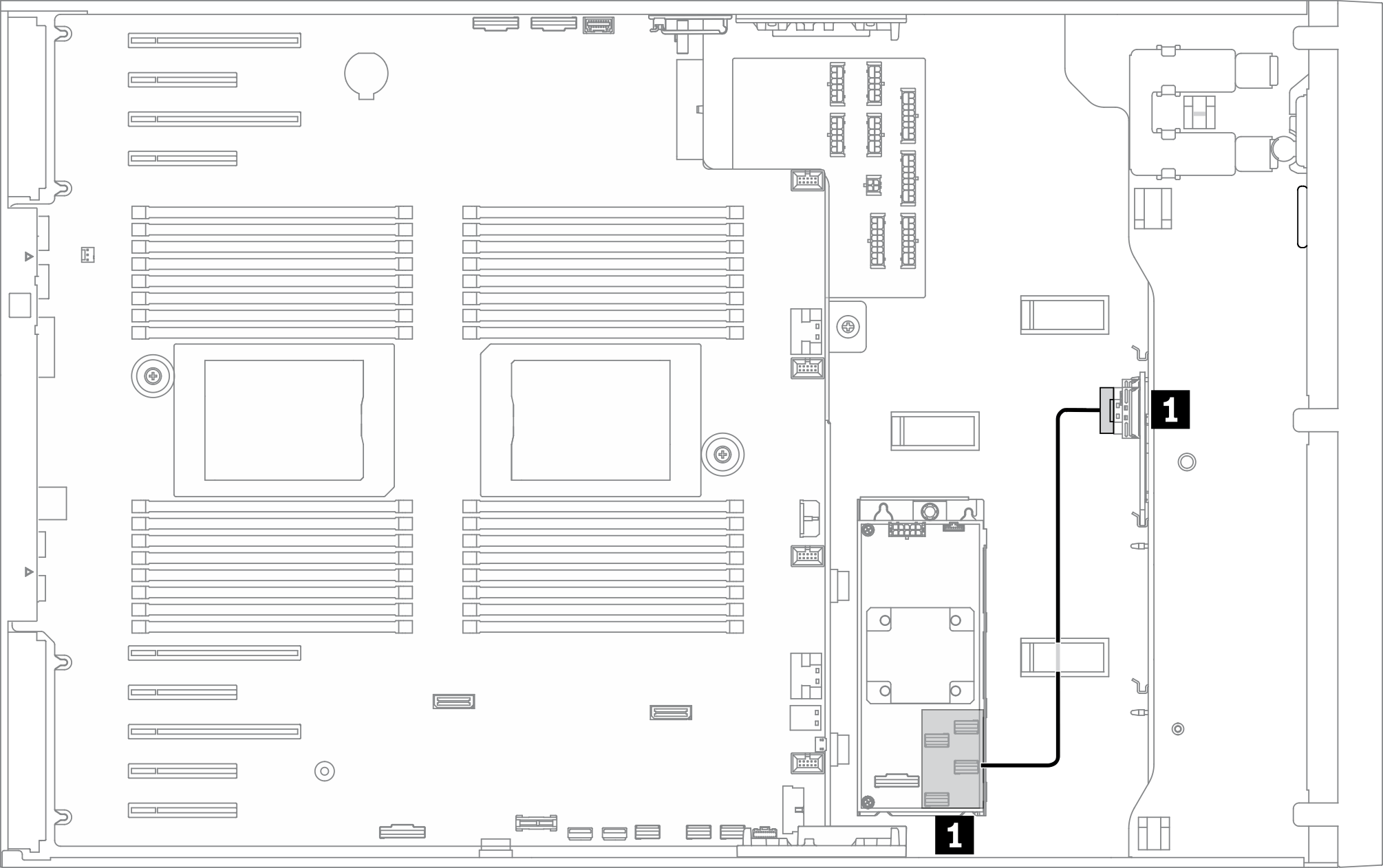 | ||
| Von | Zu | Kabel |
| 1 BP3: SAS/SATA | CFF RAID/HBA: C0, C1 | SlimSAS x4*2 zu SlimSAS x8 (430 mm/430 mm) |