Komponenten der Systemplatine
In der Abbildung in diesem Abschnitt sind die Positionen der Komponenten auf der Systemplatine dargestellt.
Abbildung 1. Komponenten der Systemplatine
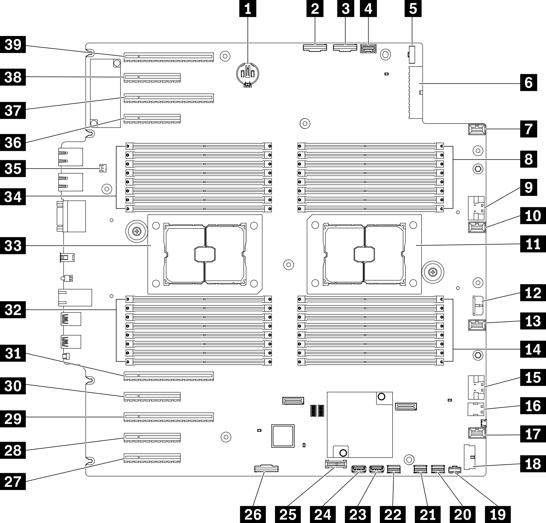
| 1 CMOS-Batterieanschluss | 21 SATA-Anschluss 0-3 |
| 2 PCIe-Anschluss 2 | 22 SATA-Anschluss 8-11 |
| 3 PCIe-Anschluss 1 | 23 Interner USB-Anschluss 3 |
| 4 Anschluss für Bedienerinformationsanzeige | 24 Interner USB-Anschluss 4 |
| 5 Signalanschluss für Stromversorgungsplatine | 25 TPM1/TCM2-Anschluss (nur chinesischer Kontinent) |
| 6 Netzanschluss für Stromversorgungsplatine | 26 Enable-Anschluss für PCIe-Steckplatz 83 |
| 7 Anschluss für Lüfter 4 | 27 PCIe-Steckplatz 9 (Prozessor 1) |
| 8 DIMM-Steckplätze 17–24 (Prozessor 2) | 28 PCIe-Steckplatz 8 (Prozessor 2)3 |
| 9 PCIe-Anschluss 3 | 29 PCIe-Steckplatz 7 (Prozessor 2) |
| 10 Anschluss für Lüfter 3 | 30 PCIe-Steckplatz 6 (Prozessor 2) |
| 11 Prozessorsockel 2 | 31 PCIe-Steckplatz 5 (Prozessor 2) |
| 12 CFF RAID-Netzteilanschluss | 32 DIMM-Steckplätze 9–16 (Prozessor 1) |
| 13 Lüfteranschluss 2 | 33 Prozessor-Sockel 1 |
| 14 DIMM-Steckplätze 25–32 (Prozessor 2) | 34 DIMM-Steckplätze 1–8 (Prozessor 1) |
| 15 PCIe-Anschluss 43 | 35 Anschluss für Schalter gegen unbefugten Zugriff |
| 16 M.2-Signalanschluss | 36 PCIe-Steckplatz 4 (Prozessor 2) |
| 17 Anschluss für Lüfter 1 | 37 PCIe-Steckplatz 3 (Prozessor 1) |
| 18 USB-Anschluss an der Vorderseite | 38 PCIe-Steckplatz 2 (Prozessor 1) |
| 19 M.2-Netzteilanschluss | 39 PCIe-Steckplatz 1 (Prozessor 1) |
| 20 SATA-Anschluss 4-7 |
Anmerkung
1 Vertrauenswürdiges Plattform-Modul
2 Trusted Cryptographic Module
3 28 PCIe-Steckplatz 8 ist standardmäßig deaktiviert. Schließen Sie den 26 Enable-Anschluss für PCIe-Steckplatz 8 an den 15 NVMe-Anschluss 4 an, um PCIe-Steckplatz 8 zu aktivieren.
Feedback geben