Dual direct link topology
This section covers details about the dual direct link topology.
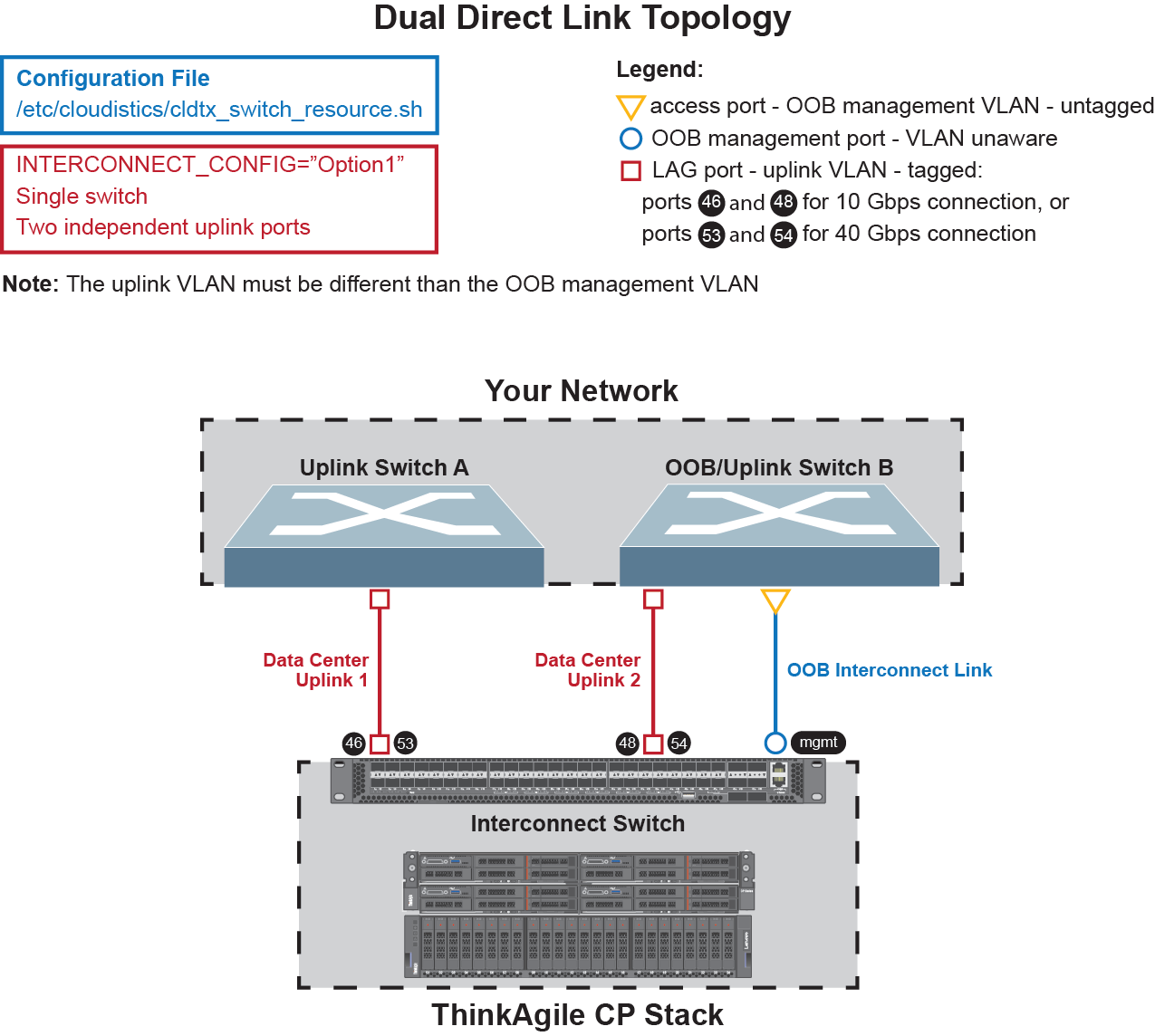
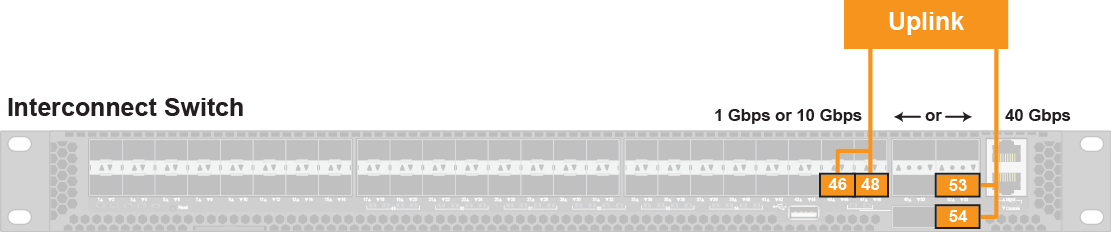
Based on the dual direct link topology and the uplink bandwidth option (10 Gbps or 40 Gbps) for the customer data center connection, use the following port connectivity diagram:
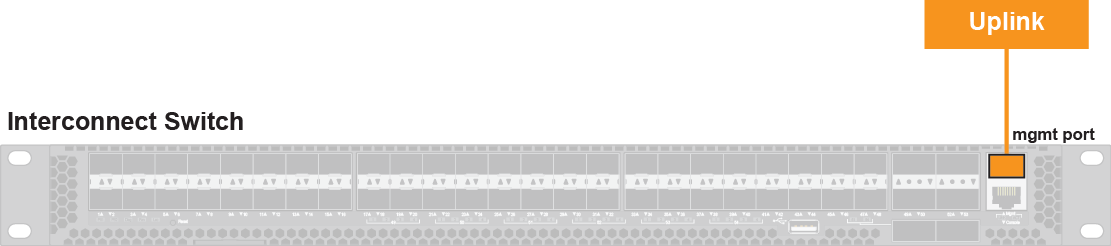
The interconnect switch requires a single 1 Gbps copper connection (RJ45) from the out-of-band (OOB) management port on the interconnect switch to the management switch or the OOB interconnect network.
Ports 51 and 54 of the interconnect switch do not have LED status indicators.
The following table provides the ports from the interconnect switch which need to be connected to the customer data center network.
Uplink bandwidth option | Device | Network interconnect ports |
|---|---|---|
10 Gbps data center network | Primary device | Interconnect, Mgmt port Interconnect, port 48 |
Secondary device | Interconnec,t port 46 | |
40 Gbps data center network | Primary device | Interconnect, Mgmt port Interconnect, port 54 |
Secondary device | Interconnect, port 53 |
Choose either the 10 Gbps or the 40 Gbps option.
Configuration | Redundant single physical trunk ports |
OOB Interconnect Network | One access port for the interconnect switch connected to the management switch or VLAN |
Requirements | STP required |
The uplink VLAN must be different than the OOB management VLAN.