Rear view
The rear of the system provides access to several connectors and components, including the power supplies and various connectors. This topic provides information about the rear view of 2U and 4U models.
Rear view of DE2000 series (2U)
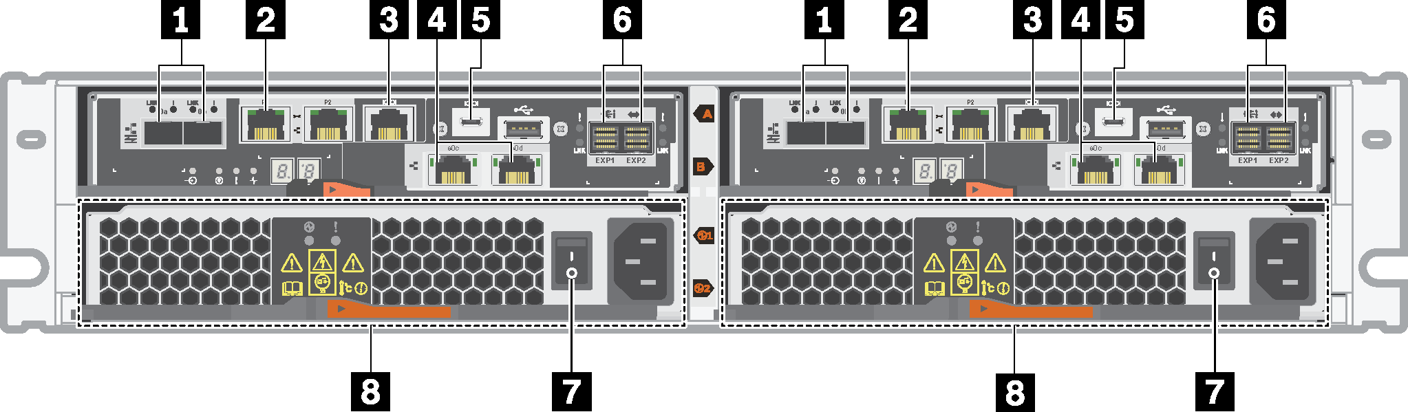
| 1 Baseboard host ports* | 2 1Gb Ethernet management port* |
| 3 RJ45 console port | 4 HIC host ports* |
| 5 Micro-B USB console port | 6 SAS expansion ports |
| 7 Power supply switch | 8 Power-fan canister |
1: Depending on the configuration, the baseboard host ports can be two 10Gb iSCSI optical ports or 16Gb Fiber Channel (FC) ports.
2: There are two Ethernet ports. The P1 port is the 1Gb Ethernet management port. The P2 port is reserved for Lenovo technical support.
4: Depending on the configuration, the optional HIC host ports can be two 10Gb Base-T ports or 12Gb SAS ports.
Rear view of DE4000 series (2U)
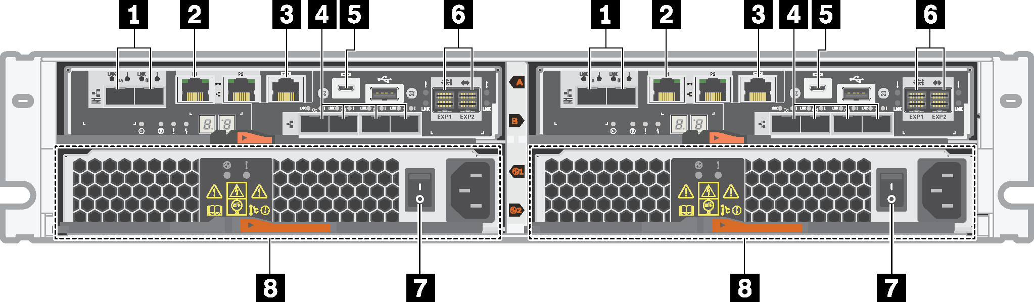
| 1 Baseboard host ports* | 2 1Gb Ethernet management port* |
| 3 RJ45 console port | 4 HIC host ports (optional)* |
| 5 Micro-B USB console port | 6 SAS expansion ports |
| 7 Power supply switch | 8 Power-fan canister |
1: Depending on the configuration, the baseboard host ports can be two 10Gb iSCSI optical ports or 16Gb FC ports.
2: There are two Ethernet ports. The P1 port is the 1Gb Ethernet management port. The P2 port is reserved for Lenovo technical support.
4: Depending on the configuration, the optional HIC host ports can be two 10Gb Base-T ports, four 12Gb SAS ports, 10Gb iSCSI optical ports, 16Gb FC ports, 10/25Gb iSCSI ports, or 32Gb FC ports.
Rear view of DE6000 series (2U)
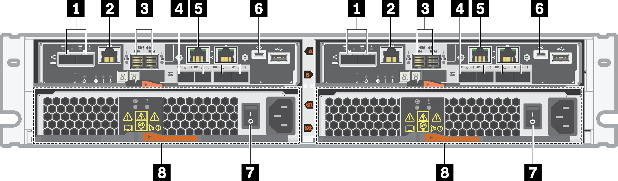
| 1 Baseboard host ports* | 2 RJ45 console port |
| 3 SAS expansion ports | 4 HIC host ports (optional)* |
| 5 1Gb Ethernet management port* | 6 Micro-B USB console port |
| 7 Power supply switch | 8 Power-fan canister |
1: Depending on the configuration, the baseboard host ports can be two 10Gb iSCSI optical ports or 16Gb FC ports. Note that when the HIC ports are configured for NVMe over Fabrics (FC or RoCE) the baseboard ports are disabled.
2: There are two Ethernet ports. The P1 port is the 1Gb Ethernet management port. The P2 port is reserved for Lenovo technical support.
4: Depending on the configuration, the optional HIC host ports can be two 100Gb NVMe-RoCE ports, four 12Gb SAS ports, 10/25Gb iSCSI optical ports, or 32Gb FC ports.
Rear view of DE120S and DE240S (2U)
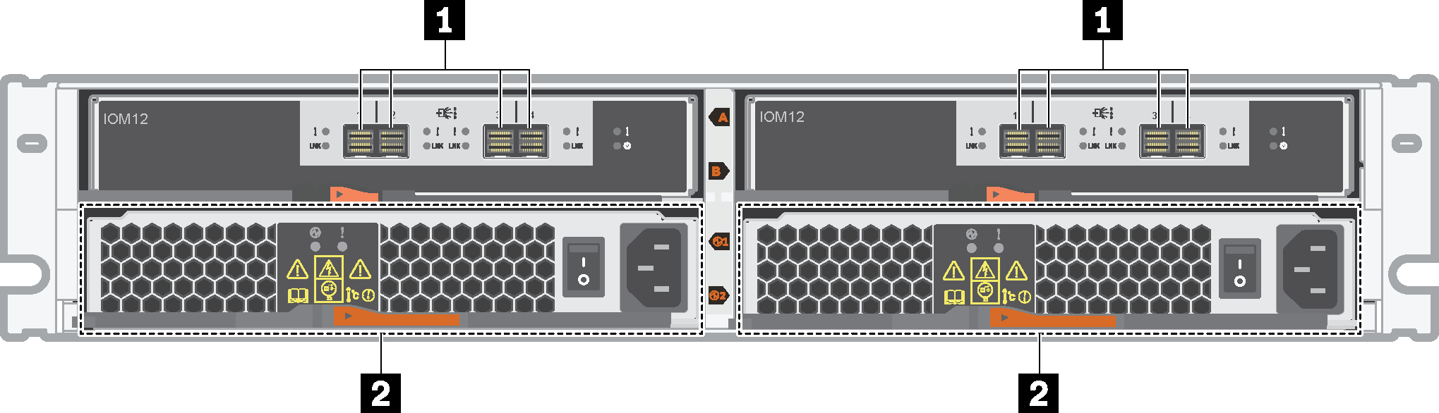
| 1 SAS ports | 2 power-fan canister |
Rear view of DE4000H (4U)
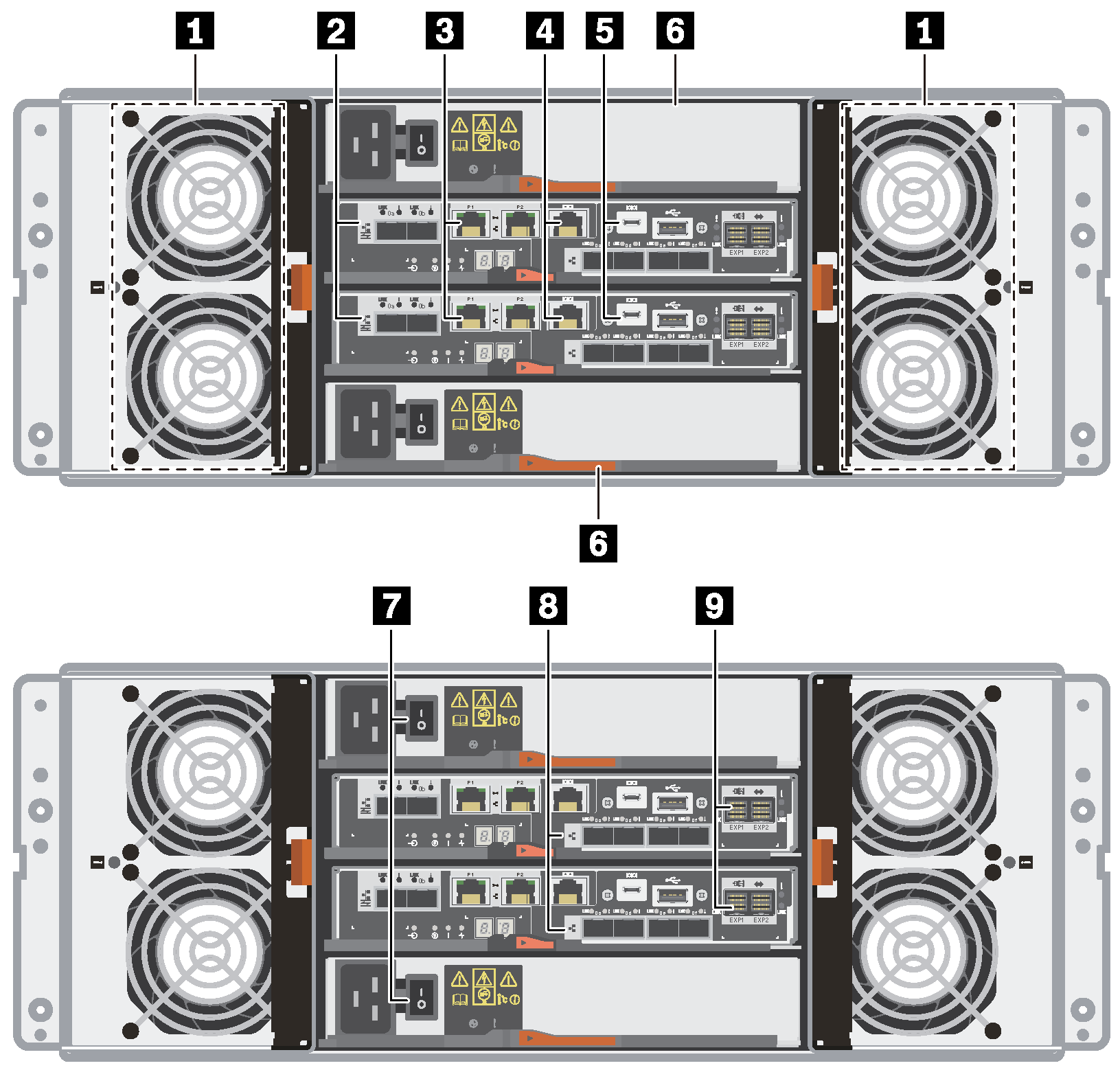
| 1 Fan canisters | 2 Baseboard host ports* |
| 3 1Gb Ethernet management ports* | 4 RJ45 console ports |
| 5 Micro-B USB console ports | 6 Power canisters |
| 7 Power supply switches | 8 HIC host ports (optional)* |
| 9 SAS expansion ports |
2: Depending on the configuration, the onboard host interface ports can be two 10Gb iSCSI optical ports or 16Gb FC ports.
3: There are four Ethernet ports. The P1 ports are the 1Gb Ethernet management ports. The P2 ports are reserved for Lenovo technical support.
8: Depending on the configuration, the optional HIC ports can be two 10Gb Base-T ports, four 10Gb iSCSI optical ports, 12Gb SAS ports, 16Gb FC ports, 25Gb iSCSI optical ports, or 32Gb FC ports.
Rear view of DE6000H (4U)
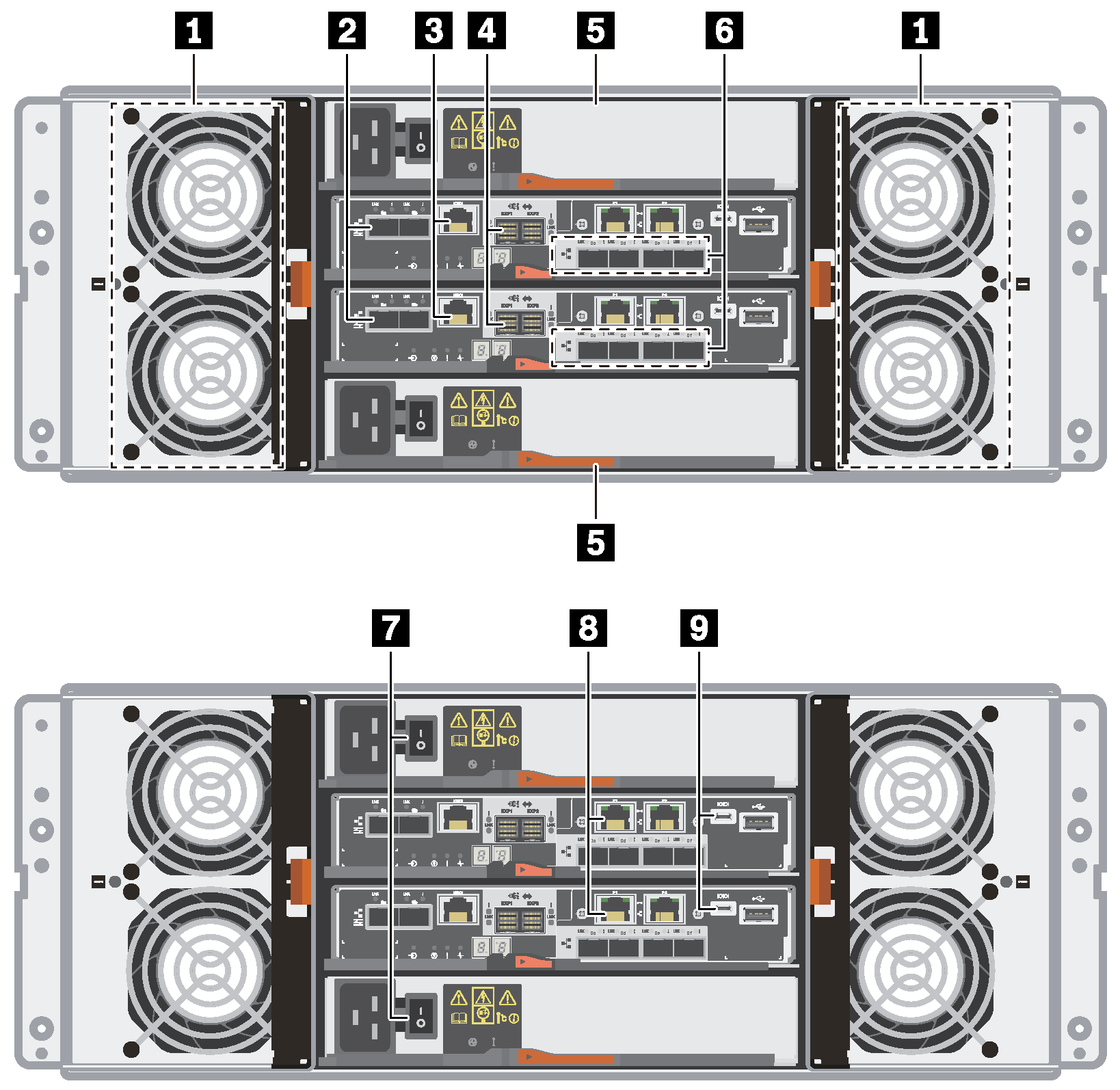
| 1 Fan canisters | 2 Baseboard host ports* |
| 3 RJ45 console ports | 4 SAS expansion ports |
| 5 Power canisters | 6 HIC host ports (optional)* |
| 7 Power supply buttons | 8 1Gb Ethernet management ports* |
| 9 Micro-B USB console ports |
2: Depending on the configuration, the onboard host interface ports can be two 10Gb iSCSI optical ports or 16Gb FC ports. Note that when the HIC ports are configured for NVMe over Fabrics (FC or RoCE) the baseboard ports are disabled.
6: Depending on the configuration, the optional HIC ports can be two 100Gb NVMe-RoCE ports, four 12Gb SAS ports, 10/25Gb iSCSI optical ports, or 32Gb FC ports.
8: There are four 1Gb Ethernet ports. The P1 ports are the 1Gb Ethernet management port. The P2 ports are reserved for Lenovo technical support.
Rear view of DE600S (4U)
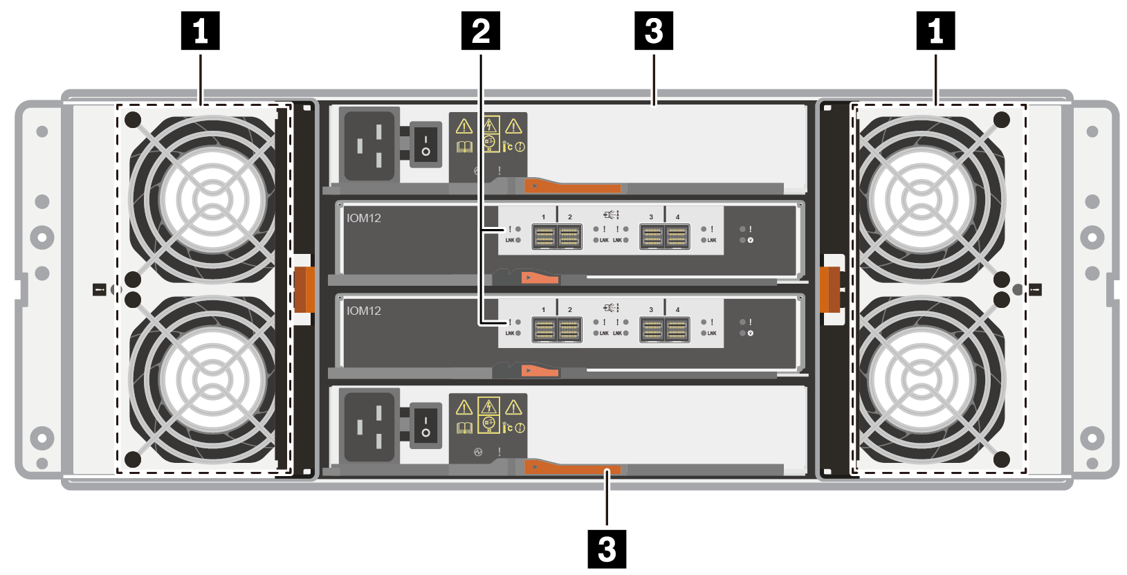
| 1 Fan canisters | 2 SAS expansion ports |
| 3 Power canisters |