Front view
The following illustration shows the controls, LEDs, and connectors on the front of the server.
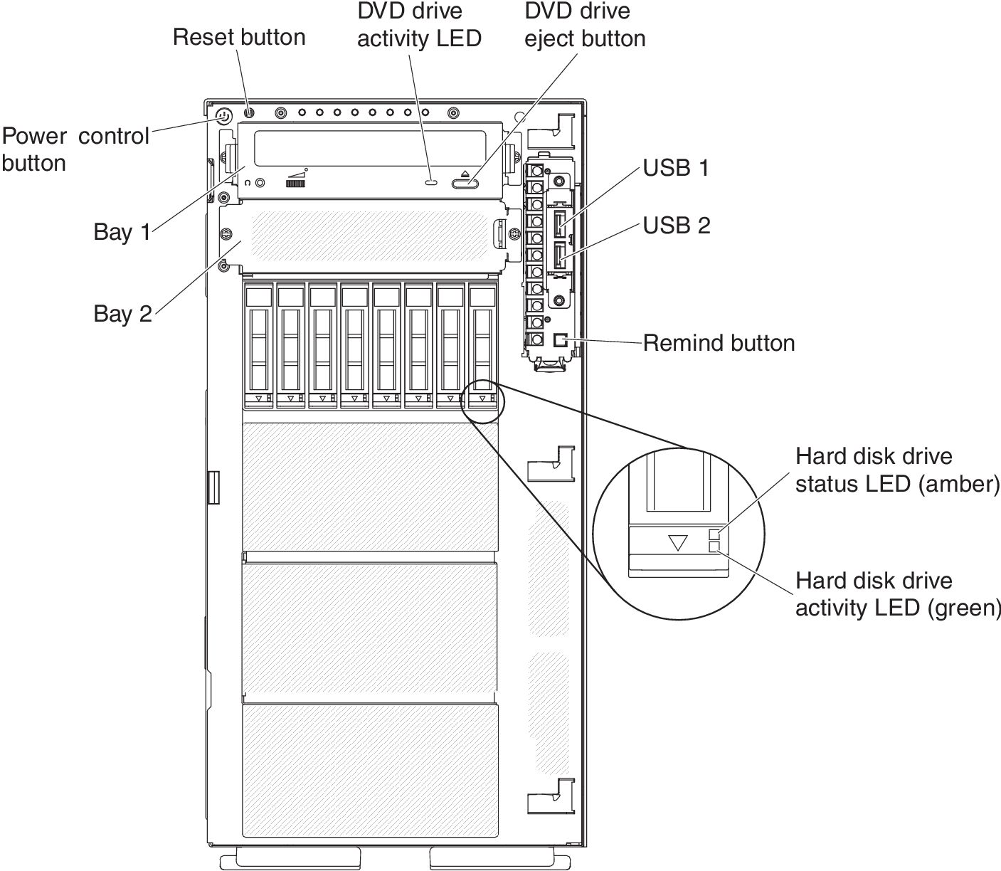
Power-control button:
Press this button to turn the server on and off manually.
Hard disk drive activity LEDs:
This LED is used on hot-swap SAS or SATA hard disk drives. Each hot-swap hard disk drive has an activity LED, and when this LED is flashing, it indicates that the drive is in use.
Hard disk drive status LEDs:
This LED is used on hot-swap SAS or SATA hard disk drives. When this LED is lit, it indicates that the drive has failed. If an optional Lenovo ServeRAID controller is installed in the server, when this LED is flashing slowly (one flash per second), it indicates that the drive is being rebuilt. When the LED is flashing rapidly (three flashes per second), it indicates that the controller is identifying the drive.
DVD drive activity LED:
When this LED is lit, it indicates that the DVD drive is in use.
DVD eject button:
Press this button to release a DVD or CD from the DVD drive.
Light path diagnostics panel:
Light path diagnostics is a system of LEDs on various external and internal components of the server. When an error occurs, LEDs are lit throughout the server. By viewing the LEDs in a particular order, you can often identify the source of the error. See Light path diagnostics panel for more information about the light path diagnostics.
Operator information panel:
This panel contains controls and LEDs that provide information about the status of the server. For information about the controls and LEDs on the operator information panel, see Operator information panel.
Remind button:
This button places the system-error LED/check log LED on the operator information panel into Remind mode. In Remind mode, the system-error LED flashes once every 2 seconds until the problem is corrected, the server is restarted, or a new problem occurs.
By placing the system-error LED indicator in Remind mode, you acknowledge that you are aware of the last failure but will not take immediate action to correct the problem. The remind function is controlled by the IMM2.
Reset button:
Press this button to reset the server and run the power-on self-test (POST). You might have to use a pen or the end of a straightened paper clip to press the button. The Reset button is in the lower-right corner of the light path diagnostics panel.
USB connectors:
Connect a USB device, such as a USB mouse or keyboard to any of these connectors.