Left-side cover/power cut-off switch assembly cable connection
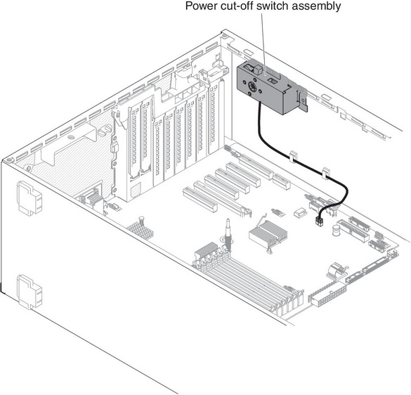
The following illustration shows the power cut-off switch assembly cable routing and the connector on the system board.
Figure 1. Power cut-off switch assembly cable routing and the connector on the system board
Give documentation feedback