System-board jumpers
This section describes the jumpers on the system board.
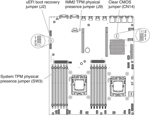
| Jumper number | Jumper name | Jumper setting |
|---|---|---|
| CN14 | Clear CMOS jumper |
Note 2 |
| J2 | UEFI boot recovery jumper |
Notes 1 and 2 |
Note
| ||
Important:
- Before you change any switch settings or move any jumpers, turn off the server; then, disconnect all power cords and external cables. (Review the information inSafety, Installation guidelines, Handling static-sensitive devices, and Turning off the server.
- Any system-board switch or jumper blocks that are not shown in the illustrations in this document are reserved.
Give documentation feedback