Front view
The following illustrations show the controls, LEDs, and connectors on the front of your server model.
Controls, LEDs, and connectors on your server model.
Figure 1. Front view: 2.5-inch hard-disk-drive bay model
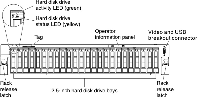
Figure 2. Front view: 2.5-inch hard-disk-drive bay and 1.8-inch solid-state-drive bay model
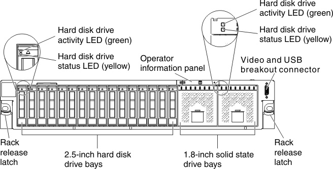
- Rack release latches: Press the latches on each front side of the server to remove the server from the rack.
- Hard disk drive activity LEDs: This LED is used on hot-swap hard disk drives. Each hot-swap hard disk drive has an activity LED, and when this LED is flashing, it indicates that the drive is in use.
- Hard disk drive status LEDs: This LED is used on hot-swap hard disk drives. When this LED is lit, it indicates that the drive has failed. If an optional ServeRAID controller is installed in the server, when this LED is flashing slowly (one flash per second), it indicates that the drive is being rebuilt. When the LED is flashing rapidly (three flashes per second), it indicates that the controller is identifying the drive.
- Operator information panel: This panel contains controls and LEDs that provide information about the status of the server. For information about the controls and LEDs on the operator information panel, see Operator information panel.
- Tag: Pull the tag forward to access the tag.
- Video and USB breakout connector: Connect the video and USB breakout cable to this connector (see Video and USB breakout cable for more information).
- Video connector (optional): Connect a monitor to this connector. The video connectors on the front and rear of the server can be used simultaneously.NoteThe maximum video resolution is 1600 x 1200 at 75 Hz.
- USB connectors (optional): Connect a USB device, such as a USB mouse or keyboard to any of these connectors.
Give documentation feedback