Light path diagnostics
Use this information as an overview of light path diagnostics.
Light path diagnostics is a system of LEDs on various external and internal components of the server that leads you to the failed component. When an error occurs, LEDs are lit along the path of the front panel, the light path diagnostics panel, then on the failed component. By viewing the LEDs in a particular order, you can often identify the source of the error.
When LEDs are lit to indicate an error, they remain lit when the server is turned off, provided that the server is still connected to power and the power supply is operating correctly.
Before you work inside the server to view light path diagnostics LEDs, read Safety and Handling static-sensitive devices.
If an error occurs, view the light path diagnostics LEDs in the following order:
- Look at the operator information panel on the front of the server:
- If the check log LED is lit, it indicates that information about an un-isolated fault condition in the server is available in the IMM2 event log or in the system-event log.
- If the system-error LED is lit, it indicates that an error has occurred; go to step 2.
The following illustration shows the operator information panel.
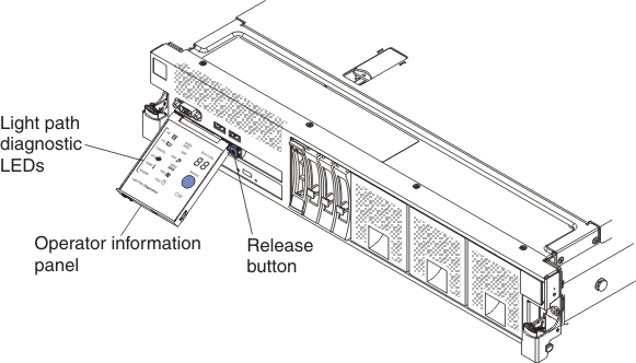
- To view the light path diagnostics panel, press in on the blue release button on the operator information panel and pull forward on the panel until the hinge of the operator information panel is free of the server chassis. Then, pull down on the panel so that you can view the light path diagnostics panel information. This reveals the light path diagnostics panel. Lit LEDs on this panel indicate the type of error that has occurred.
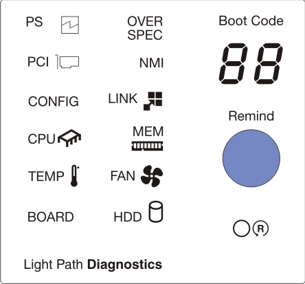
The following illustration shows the light path diagnostics panel.
Note any LEDs that are lit, and then slide the light path diagnostics panel back into the server.
- Boot code display: This display provides an error code that indicates the point at which the system stopped during the boot block and POST. A boot code is either a byte or a word value that is produced by UEFI. This display will provide error codes in the event of a microprocessor error or a power fault. In addition to the IMM log, the codes can provide suggested components to be replaced. For more information about the error codes displayed in the boot code display area on the light path diagnostics panel and the actions to take, see Boot code display error codes.
- Remind button: Press this button to place the system-error LED on the front information panel into Remind mode. By placing the system-error LED indicator in Remind mode, you acknowledge that you are aware of the last failure but will not take immediate action to correct the problem. In Remind mode, the system-error LED flashes every 2 seconds until one of the following conditions occurs:
- All known errors are corrected.
- The server is restarted.
- A new error occurs, causing the system-error LED to be lit again.
- Reset button: Press this button to reset the server and run the power-on self-test (POST). You might have to use a pen or the end of a straightened paper clip to press the button. The Reset button is in the lower-right corner of the light path diagnostics panel.
The system service label inside the server cover provides an overview of internal components that correspond to the LEDs on the light path diagnostics panel. This information and the information in Light path diagnostics LEDs can often provide enough information to diagnose the error.
- Remove the server cover and look inside the server for lit LEDs. Certain components inside the server have LEDs that are lit to indicate the location of a problem.NoteYou do not have to remove the server cover to view the LEDs on hard disk drives and power supplies.
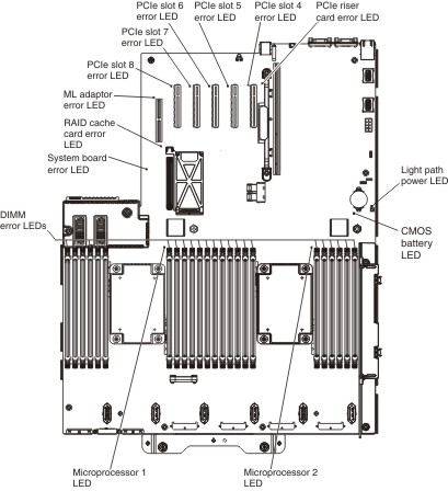
The following illustration shows the LEDs and connectors on the system board.
The following illustration shows the LEDs on the optional microprocessor and memory expansion tray.
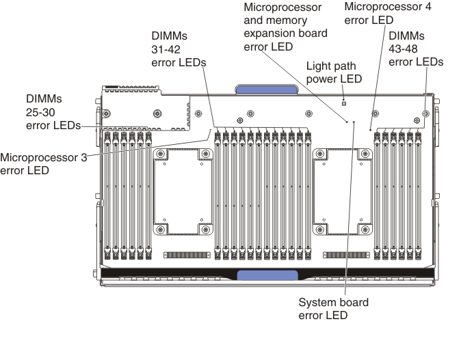
Table 1. Microprocessor and memory expansion tray LEDs. LEDs Description Light path power LED When this LED is lit, it indicates that the capacitor on the microprocessor and memory expansion tray has sufficient power to light the error LEDs. Microprocessor and memory expansion tray board error LED When this LED is lit, it indicates that the microprocessor and memory expansion tray board has failed. System board error LED When this LED is lit, it indicates that an error has occurred on the base system board.