メインコンテンツまでスキップ

IBM to Lenovo server upgrade procedure

This topic describes how to perform the IBM to Lenovo (ITL) upgrade of an IBM System x3850 X6 and x3950 X6 Type 3837 server to a Lenovo System x3850 X6 and x3950 X6 Type 6241 server.

Installing an IBM to Lenovo (ITL) upgrade kit in an IBM System x3850 X6 and x3950 X6 Type 3837 server upgrades it to a Lenovo System x3850 X6 and x3950 X6 Type 6241 server, allowing the server to receive the latest system updates and improvements from Lenovo.

Attention
Installation of the ITL kit must be performed by a Lenovo-approved service technician.

Upgrade task summary

Several processes need to be completed to perform an IBM to Lenovo server upgrade. Some tasks must be completed to prepare for the upgrade in advance of performing the actual upgrade. Each task is described in detail by the sub-topics following the task summary.

  • In advance of performing the ITL upgrade, the customer needs to complete the following tasks:

    • Order the ITL upgrade kit for the server.

    • Verify access to IBM websites.

    • Request transfer of Features on Demand (FoD) keys or new FoD keys.

  • When the service technician is ready to perform the ITL upgrade, they will need to complete the following tasks before they begin:

    • Download the latest versions of IBM and Lenovo software tools needed to perform the ITL upgrade.

    • Make sure that the FoD key transfer was completed or that new FoD keys were received.

    • Verify the contents of the ITL upgrade kit.

    • Record the system information needed to upgrade the Lenovo service agreements.

    • Backup the IBM server configuration and vital product data (VPD).

  • To perform the ITL upgrade, service technician will complete the following tasks:

    • Replace IBM components with the Lenovo components included in the ITL upgrade kit.

    • Update server firmware to the latest Lenovo version.

    • Restore the server configuration and VPD.

    • Restore the transferred FoD keys or install the new FoD keys.

    • Relabel the server as a Lenovo server.

  • After the ITL upgrade is complete, the service technician will verify that the conversion is successful and update the customer records.

Preparing for the upgrade

Before a a service technician can begin upgrading a customer server, the customer must complete the following tasks, in advance:

  1. Order the correct ITL kit for the Lenovo x3850 X6 or Lenovo x3950 X6 server.

  2. Verify that the customer IDs and passwords are valid for the IBM Support portal (http://www.ibm.com/support/), IBM Fix Central (http://www.ibm.com/support/fixcentral/), and the Features on Demand (FoD) website (https://fod.lenovo.com/lkms). The customer will need to access these IBM websites to download tools and information for their IBM server before the service technician can perform the upgrade.

  3. If any Features on Demand (FoD) options or features are being used in the IBM server, the customer must complete the following steps to manually transfer or request new FoD keys for use in the Lenovo server:

    1. Make a list of all the FoD activation keys that are active for the IBM server. Select Retrieve history at the Features on Demand website (https://www.ibm.com/systems/x/fod) to view the active keys for the IBM server.

    2. Verify which FoD are installed in the IBM server (see the IBM Integrated Management Module II User's Guide at https://www.ibm.com/support/entry/portal/docdisplay?lndocid=MIGR-5086346 for information about how to check if FoD keys are installed in the server and instructions about how to import and export the FoD keys).

    3. Request a manual transfer of the FoD activation keys from the original IBM machine type to the new Lenovo machine type, or request new FoD activation keys for use with the new Lenovo machine type. To request a manual transfer or new activation keys, the customer must send an email request to Features on Demand Support at fod@lenovo.com. Make sure that this email includes a reference to the ITL kit and provides the following information:

      • The original IBM server serial number.

      • The machine type of the original IBM server (Type 3837).

      • The machine type of the upgraded Lenovo server (Type 6241).

      • A list of the FoD activation keys to transfer or replace, that were gathered in step 3a.

Before you begin

Before the service technician can begin physically upgrading the server, the customer and service technician must complete the following tasks:

  1. Download the following software tools and associated documentation. Both IBM and Lenovo tools are needed to backup and restore the server configuration. IBM tools will be used to backup server configuration information in preparation for the ITL upgrade. Lenovo tools will be used to restore server configuration information after the ITL upgrade.

  2. Verify that the IBM Features on Demand activation keys that were previously requested for transfer or replacement are available to install on the upgraded Lenovo server.

  3. Verify the contents of the ITL upgrade kit:

    • The Lenovo x3850 X6 ITL upgrade kit contains:

      • One standard I/O book

      • One 4U-high right EIA bezel with Lenovo logo

      • One service card

      • System information update labels

      • One MAC address label

    • The Lenovo x3950 X6 ITL upgrade kit contains:

      • Two standard I/O books

      • One 8U-high right EIA bezel with Lenovo logo

      • One service card

      • System information update labels

      • Two MAC address labels

  4. Record (take a photograph of the barcode label or write down the barcode number) the 11S serial number for each Lenovo standard I/O book that comes with the ITL kit. This is required to update the customer entitlement and service offering support.

    Note
    You will need the server IMM IP address, user name, and password to perform the following step. If you are upgrading a x3950 server, you will need the IP address for both IMMs.
  5. Using the IBM Advanced Settings Utility (ASU) tool, backup (export) the system configuration, Features on Demand (FoD) keys, and vital product data (VPD) for the IBM server.

    Note
    See the IBM Integrated Management Module II User's Guide at https://www.ibm.com/support/entry/portal/docdisplay?lndocid=MIGR-5086346 and the IBM Advanced Settings Utility User's Guide at http://toolscenter.lenovofiles.com/help/topic/asu/asu_guide.pdf for information about how to use these tools and commands.
    • Access the IBM ASU tool

      Access the IBM ASU tool by completing the following steps:

      Note
      For an IBM System x3950 X6 8-socket system, the following procedure must be performed twice, once for each of the standard I/O books in the system.
      1. Connect a laptop computer to the IMM management network port of the server.

      2. Configure your laptop operating system network settings to match the IMM network settings.

      3. Open a command prompt and navigate to the directory where the ASU files are installed.

      Note
      To run the ASU commands, you must be in the directory where the ASU files are installed.
    • Backup system configuration

      To backup the system configuration of the IBM server to a file, use the ASU save <filename> command, where <filename> is the complete path name of the file where the configuration is to be saved.

    • Backup Features on Demand (FoD) keys

      To backup the Features on Demand (FoD) keys of the IBM server:
      • To export the FoD inventory information for the IBM server, use the ASU fodcfg reportkey command.

      • To export the FoD keys for the IBM server, use the ASU fodcfg exportkey command.

    • Backup vital product data (VPD)

      Note
      • Make sure that you are using the latest version of the IBM ASU tool.

      • For an IBM System x3950 X6 8-socket system, the following procedure must be performed twice, once for each of the standard I/O books in the system.

      To backup the VPD data for the IBM server:

      • To save the VPD information for an IBM System x3850 X6 4–socket system, complete the following steps. Save the files in secure location, as the values they contain will need to be re-entered after installing the new Lenovo standard I/O book.

        1. To save the system VPD information into a file, run the ASU command:

          asu64 show SYSTEM_PROD_DATA --host <IMM IP> --user <IMM userid> --password <IMM password> > <serial>_system.txt

          where:

          • <IMM IP> is the IMM IP address
          • <IMM userid> is the IMM user name
          • <IMM password> is the IMM password
          • <serial> is the serial number of the standard I/O book (allows each data file to be identified)
        2. To save the system component VPD information into a file, run the ASU command:

          asu64 show VPD --host <IMM IP> --user <IMM userid> --password <IMM password> > <serial>_component.txt

          where:

          • <IMM IP> is the IMM IP address
          • <IMM userid> is the IMM user name
          • <IMM password> is the IMM password
          • <serial> is the serial number of the standard I/O book (allows each data file to be identified)
      • To save the VPD information for an IBM System x3950 X6 8–socket system, complete the following procedures. Save the files in secure location, as the values they contain will need to be re-entered after installing the new Lenovo standard I/O books.

        • To save the system VPD information for node 1 of an IBM System x3950 X6 8–socket system, complete the following steps:

          1. To save the system VPD information for node 1 into a file, run the ASU command:

            asu64 show SYSTEM_PROD_DATA --host <IMM IP> --user <IMM userid> --password <IMM password> > <serial>_Node1_system.txt

            where:

            • <IMM IP> is the IMM IP address
            • <IMM userid> is the IMM user name
            • <IMM password> is the IMM password
            • <serial> is the serial number of the standard I/O book (allows each data file to be identified)
          2. To save the system component VPD information for node 1 into a file, run the ASU command:

            asu64 show VPD --host <IMM IP> --user <IMM userid> --password <IMM password> > <serial>_Node1_component.txt

            where:

            • <IMM IP> is the IMM IP address
            • <IMM userid> is the IMM user name
            • <IMM password> is the IMM password
            • <serial> is the serial number of the standard I/O book (allows each data file to be identified)
        • To save the system VPD information for node 2 of an IBM System x3950 X6 8–socket system, complete the following steps:

          1. To save the system VPD information for node 2 into a file, run the ASU command:

            asu64 show SYSTEM_PROD_DATA --host <IMM IP> --user <IMM userid> --password <IMM password> > <serial>_Node2_system.txt

            where:

            • <IMM IP> is the IMM IP address
            • <IMM userid> is the IMM user name
            • <IMM password> is the IMM password
            • <serial> is the serial number of the standard I/O book (allows each data file to be identified)
          2. To save the system component VPD information for node 2 into a file, run the ASU command:

            asu64 show VPD --host <IMM IP> --user <IMM userid> --password <IMM password> > <serial>_Node2_component.txt

            where:

            • <IMM IP> is the IMM IP address
            • <IMM userid> is the IMM user name
            • <IMM password> is the IMM password
            • <serial> is the serial number of the standard I/O book (allows each data file to be identified)
  6. Make sure that the server is operating correctly and that there are no errors messages (see Error messages). Correct any problems that are indicated, unless they relate to components or firmware being replaced as part of the ITL upgrade.

Perform the ITL upgrade

Attention
Installation of the ITL kit must be performed by a Lenovo-approved service technician.

To upgrade an IBM server to a Lenovo server, the service technician must complete the following steps:

  1. Mark and disconnect all cables from the IBM standard I/O books.
  2. Replace each IBM standard I/O book, originally installed in the server, with a Lenovo standard I/O book, that comes with the ITL kit (see Replacing the standard I/O book for information and instructions).
    Note
    The service technician will need to perform this procedure twice when upgrading an IBM x3950 X6 server to a Lenovo x3950 X6 server.
    1. Remove the IBM standard I/O book from the shuttle (see Removing the standard I/O book for instructions).
      Important
      Before opening the release levers to extract the standard I/O book from the system, look for missing or broken tabs on the chassis that the release levers pry against. Missing or broken tabs can make removal of the standard I/O book from the chassis difficult. If tabs are missing or broken, open an online service request at the Service requests and PMRs website.
    2. Transfer components and devices (adapters, fans, USB embedded hypervisor flash device, and flash power modules) from the IBM standard I/O book, originally installed in the server, to the new Lenovo standard I/O book, that comes with the ITL kit (see Replacing the standard I/O book for instructions).
      Important
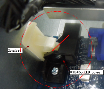
      • When installing the standard I/O book in the system, look for missing or broken tabs on the chassis that the release levers pry against. Missing or broken tabs can make installation of the standard I/O book in the chassis difficult. If tabs are missing or broken, open an online service request at the Service requests and PMRs website.

      • Check for the white bracket (stuck to mechanical wall under the air baffle). If it is present, remove it.

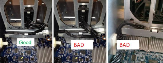
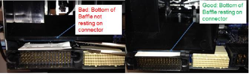
      • Make sure that the standard I/O book air baffle is fully seated, as shown in the following illustration, before installing the standard I/O book in the chassis. You might need to adjust placement of the fan cables to fully seat the air baffle. 

  3. Install the Lenovo standard I/O book in the system (see Replacing the standard I/O book for instructions).
    Note
    • Make sure that all of the feet (mounted on bottom side standard I/O book) engage the slots in the mechanical assembly.

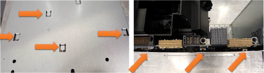
    • Check the fan cable of the standard I/O book and make sure that it is properly seated in the channel slot.

  4. Make sure that the Lenovo firmware is updated to the latest level (see Updating the firmware for information).
  5. Make sure that the UUID and DMI/SMBIOS data is updated (see Updating the Universal Unique Identifier and DMI/SMBIOS data for information).
  6. Using the Lenovo Advanced Settings Utility (ASU) tool, restore the system configuration, vital product data (VPD), and Features on Demand (FoD) keys to the upgraded Lenovo server.
    Note
    See the Lenovo Integrated Management Module II InfoCenter at http://systemx.lenovofiles.com/help/topic/com.lenovo.sysx.imm2.doc/product_page.html and the Lenovo Advanced Settings Utility InfoCenter at http://toolscenter.lenovofiles.com/help/topic/asu_lenovo/asu_main.html for information about how to use these tools.
    • Access the Lenovo ASU tool

      Access the Lenovo ASU tool by completing the following steps:

      Note
      For a Lenovo System x3950 X6 8-socket system, the following procedure must be performed twice, once for each of the standard I/O books in the system.
      1. Connect a laptop computer to the IMM management network port of the server.

      2. Configure your laptop operating system network settings to match the IMM network settings.

      3. Open a command prompt and navigate to the directory where the ASU files are installed.

      Note
      To run the ASU commands, you must be in the directory where the ASU files are installed.
    • Restore system configuration

      To restore the saved system configuration to the Lenovo server:

      1. Restore the saved system configuration using the ASU restore <filename> command, where <filename> is the complete path name of the file where the configuration was saved.

      2. Restore the original IMM IP address, user name, and password. If upgrading an x3950 server, you will need to restore this information for both IMMs.

    • Restore Features on Demand (FoD) keys

      Import the transferred or newly purchased FoD keys to the upgraded Lenovo server using the ASU fodcfg installkey command.

    • Restore vital product data (VPD)

      Note
      • Make sure that you are using the latest version of the Lenovo ASU.

      • Make copies of the original VPD files captured from the IBM server before you begin making modifications. If you make any mistakes when creating the batch files for restoring VPD to the Lenovo server, these copies will allow you to start over.

      • For a Lenovo System x3950 X6 8-socket system, the following procedure must be performed twice, once for each of the standard I/O books in the system.

      To modify and restore the saved IBM vital product data (VPD) to the Lenovo server, create and run batch files using the Lenovo Advanced Settings Utility (ASU) as described in the following tasks.

      Create a VPD upgrade batch file

      The batch files for Lenovo System x3850 X6 4-socket and Lenovo System x3950 X6 8-socket systems are different.

      • To create a VPD batch file for a Lenovo System x3850 X6 4-socket system:

        1. Open a new <serial>_system.bat file (where <serial> is the serial number of the standard I/O book, allowing each batch file to be identified). This file will be edited to create a VPD update batch file.

        2. Complete the following steps to add commands to the <serial>_system.bat file:

          1. Open the <serial>_system.txt file (where <serial> is the serial number of the standard I/O book). This file was saved from the IBM System x3850 X6 4-socket system during the Backup vital product data (VPD) procedure.

          2. Locate the IBM server machine type and model string in the <serial>_system.txt file. This string has the following format:

            SYSTEM_PROD_DATA.SysInfoProdName=<IBM_machine_type_model>

            where: <IBM_machine_type_model> is a 7–character field that combines the 4–character machine type and the 3–character model number.

          3. Change the IBM server machine type to the Lenovo server machine type by replacing the IBM server 4-character machine type, 3837, with the Lenovo server 4-character machine type, 6241. The 3-character model number remains unchanged between the IBM and Lenovo servers.

            For example, if the original IBM server machine type and model number was 3837FT4, the new Lenovo server machine type and model number would be 6241FT4.

          4. Add a command line to the batch file for the Lenovo server machine type and model created in the previous step. (this model number varies based on the original IBM server model number), following the form:

            asu64 set SYSTEM_PROD_DATA.SysInfoProdName <Lenovo_machine_type_model> --host <IMM_IP> --user <IMM_userid> --password <IMM_password>

            where:
            • <Lenovo_machine_type_model> is a 7–character field that combines the new Lenovo 4–character machine type and the original IBM 3–character model number

            • <IMM_IP> is the IMM IP address

            • <IMM_userid> is the IMM user name

            • <IMM_password> is the IMM password

          5. Add a command line to the batch file for the Lenovo server product identifier, following the form:

            asu64 set SYSTEM_PROD_DATA.SysInfoProdIdentifierEx “<product_id>” --override --host <IMM_IP> --user <IMM_userid> --password <IMM_password>

            where:
            • <product_id> is Lenovo System x3850 X6 for 4-socket systems

            • <IMM_IP> is the IMM IP address

            • <IMM_userid> is the IMM user name

            • <IMM_password> is the IMM password

          6. Locate the IBM server serial number in the <serial>_system.txt file. This string has the following format:

            SYSTEM_PROD_DATA.SysInfoSerialNum=<serial_number>

            where: <serial_number> is a 7–character field for the product serial number.

            Note
            The Lenovo server system serial number remains unchanged: it is the same serial number that was used for the IBM server.
          7. Add a command line to the batch file for the Lenovo server serial number, following the form:

            asu64 set SYSTEM_PROD_DATA.SysInfoSerialNum <serial_number> --host <IMM_IP> --user <IMM_userid> --password <IMM_password>

            where:
            • <serial_number> is a 7–character field for the product serial number (the Lenovo server and the IBM server use the same serial number)

            • <IMM_IP> is the IMM IP address

            • <IMM_userid> is the IMM user name

            • <IMM_password> is the IMM password

          8. Add a command line to the batch file for the Lenovo server UUID, following the form:

            asu64 set SYSTEM_PROD_DATA.SysInfoUUID <uuid> --host <IMM_IP> --user <IMM_userid> --password <IMM_password>

            where:
            • <uuid> is a 16–character hexadecimal field for the server UUID
              • Contact the customer to determine if the original UUID value should be used or if a new UUID value should be generated for the upgraded server.

              • If needed, locate the original IBM server UUID in the <serial>_system.txt file. This string has the following format:

                SYSTEM_PROD_DATA.SysInfoUUID=<uuid>

            • <IMM_IP> is the IMM IP address

            • <IMM_userid> is the IMM user name

            • <IMM_password> is the IMM password

          9. Open the <serial>_component.txt file (where <serial> is the serial number of the standard I/O book). This file was saved from the IBM System x3850 X6 4-socket system during the Backup vital product data (VPD) procedure.

          10. Locate the IBM server component part numbers in the <serial>_component.txt file. There are multiple component part numbers in the following format:

            VPD.CompVPD_PartNumber.# <p/n>

            where:

            • # is the component numeric identifier:
              • 1 for the 4–socket midplane
              • 3 for the front I/O panel assembly
              • 4 for LCD display panel
            • <p/n> is a 7–character component part number

            Note
            • The Lenovo server component part numbers remain unchanged: they are the same part numbers that were used in the IBM server.

            • The component part number is the first six characters following the “11S” of the 11S barcode. In the following example, the part number is shown in bold:

              11S12X4567YJ1105A34567

          11. Add a command line to the batch file for each Lenovo server component part number, following the form:

            asu64 set VPD.CompVPD_PartNumber.#<p/n>[sp][sp][sp][sp][sp]” --host <IMM_IP> --user <IMM_userid> --password <IMM_password>

            where:
            • # is the component numeric identifier:
              • 1 for the 4–socket midplane
              • 3 for the front I/O panel assembly
              • 4 for LCD display panel
            • <p/n> is the first 7–characters of a 12–character field, followed by five padding spaces, for the component part number (the Lenovo server and the IBM server use the same component part numbers)

            • <IMM_IP> is the IMM IP address

            • <IMM_userid> is the IMM user name

            • <IMM_password> is the IMM password

          12. Locate the IBM server component FRU part numbers in the <serial>_component.txt file. There are multiple component FRU part numbers in the following format:

            VPD.CompVPD_FRUNumber.# <fru_number>

            where:

            • # is the component numeric identifier:
              • 1 for the 4–socket midplane
              • 3 for the front I/O panel assembly
              • 4 for LCD display panel
            • <fru_number> is a 7–character FRU part number

            Note
            The Lenovo server component FRU part numbers remain unchanged: they are the same FRU numbers that were used in the IBM server.
          13. Add a command line to the batch file for each Lenovo server component FRU part number, following the form:

            asu64 set VPD.CompVPD_FRUNumber.#<fru_number>[sp][sp][sp][sp][sp]” --host <IMM_IP> --user <IMM_userid> --password <IMM_password>

            where:
            • # is the component numeric identifier:
              • 1 for the 4–socket midplane
              • 3 for the front I/O panel assembly
              • 4 for LCD display panel
            • <fru_number> is the first 7–characters of a 12–character field, followed by five padding spaces, for the component FRU part number (the Lenovo server and the IBM server use the same component FRU numbers)

            • <IMM_IP> is the IMM IP address

            • <IMM_userid> is the IMM user name

            • <IMM_password> is the IMM password

          14. Locate the IBM server component serial numbers in the <serial>_component.txt file. There are multiple component serial numbers in the following format:

            VPD.CompVPD_SerialNumber.# <s/n>

            where:

            • # is the component numeric identifier:
              • 1 for the 4–socket midplane
              • 3 for the front I/O panel assembly
              • 4 for LCD display panel
              Note
              A serial number for the front I/O panel assembly (3) is not required and might not be listed.
            • <s/n> is a 6–character component serial number

            Note
            • The Lenovo server component serial numbers remain unchanged: they are the same serial numbers that were used in the IBM server.

            • The serial number is the last six characters of the 11S barcode. In the following example, the serial number is shown in bold:

              11S12X4567YJ1105A34567

          15. Add a command line to the batch file for each Lenovo server component serial number, following the form:

            asu64 set VPD.CompVPD_SerialNumber.# <s/n> --host <IMM_IP> --user <IMM_userid> --password <IMM_password>

            where:
            • # is the component numeric identifier:
              • 1 for the 4–socket midplane
              • 3 for the front I/O panel assembly
              • 4 for LCD display panel
              Note
              A serial number for the front I/O panel assembly (3) is not required.
            • <s/n> is a 6–character component serial number (the Lenovo server and the IBM server use the same component serial numbers)

            • <IMM_IP> is the IMM IP address

            • <IMM_userid> is the IMM user name

            • <IMM_password> is the IMM password

          16. Locate the IBM server component serial number prefixes in the <serial>_component.txt file. There are multiple component serial number prefixes in the following format:

            VPD.CompVPD_PrefixSerialNumber.# <prefix_s/n>

            where:

            • # is the component numeric identifier:
              • 1 for the 4–socket midplane
              • 3 for the front I/O panel assembly
              • 4 for LCD display panel
              Note
              A serial number for the front I/O panel assembly (3) is not required and might not be listed.
            • <prefix_s/n> is a 6–character component serial number prefix

            Note
            • The Lenovo server component serial numbers remain unchanged: they are the same serial numbers that were used in the IBM server.

            • The serial number prefix is the six characters of the 11S barcode that follow the first 10 characters of the 11S barcode (the six characters preceding the component serial number portion of the 11S barcode). In the following example, the serial number prefix is shown in bold:

              11S12X4567YJ1105A34567

          17. Add a command line to the batch file for each Lenovo server component serial number prefix, following the form:

            asu64 set VPD.CompVPD_PrefixSerialNumber.# <prefix_s/n>--host <IMM_IP> --user <IMM_userid> --password <IMM_password>

            where:
            • # is the component numeric identifier:
              • 1 for the 4–socket midplane
              • 3 for the front I/O panel assembly
              • 4 for LCD display panel
              Note
              A serial number for the front I/O panel assembly (3) is not required.
            • <prefix_s/n> is a 6–character component serial number prefix (the Lenovo server and the IBM server use the same component serial number prefixes)

            • <IMM_IP> is the IMM IP address

            • <IMM_userid> is the IMM user name

            • <IMM_password> is the IMM password

          Note
          To view an example VPD batch file, see IBM to Lenovo server upgrade batch file examples.
        3. Save and close the file.

      • The Lenovo System x3950 X6 8-socket system requires separate batch files for each node.

        • To create a VPD batch file for node 1 of a Lenovo System x3950 X6 8-socket system:

          1. Open a new <serial>_Node1_system.bat file (where <serial> is the serial number of the standard I/O book in node 1, allowing each batch file to be identified). This file will be edited to create a VPD update batch file for node 1.

          2. Complete the following steps to add commands to the <serial>_Node1_system.bat file:

            1. Open the <serial>_Node1_system.txt file (where <serial> is the serial number of the standard I/O book in node 1). This file was saved from node 1 of the IBM System x3950 X6 8-socket system during the Backup vital product data (VPD) procedure.

            2. Locate the IBM server machine type and model string in the <serial>_Node1_system.txt file. This string has the following format:

              SYSTEM_PROD_DATA.SysInfoProdName=<IBM_machine_type_model>

              where: <IBM_machine_type_model> is a 7–character field that combines the 4–character machine type and the 3–character model number.

            3. Change the IBM server machine type to the Lenovo server machine type by replacing the IBM server 4-character machine type, 3837, with the Lenovo server 4-character machine type, 6241. The 3-character model number remains unchanged between the IBM and Lenovo servers.

              For example, if the original IBM server machine type and model number was 3837FT4, the new Lenovo server machine type and model number would be 6241FT4.

            4. Add a command line to the batch file for the Lenovo server machine type and model created in the previous step (this model number varies based on the original IBM server model number), following the form:

              asu64 set SYSTEM_PROD_DATA.SysInfoProdName <Lenovo_machine_type_model> --host <IMM_IP> --user <IMM_userid> --password <IMM_password>

              where:
              • <Lenovo_machine_type_model> is a 7–character field that combines the new Lenovo 4–character machine type and the original IBM 3–character model number

              • <IMM_IP> is the IMM IP address

              • <IMM_userid> is the IMM user name

              • <IMM_password> is the IMM password

            5. Add a command line to the batch file for the Lenovo server product identifier, following the form:

              asu64 set SYSTEM_PROD_DATA.SysInfoProdIdentifierEx “<product_id>” --override --host <IMM_IP> --user <IMM_userid> --password <IMM_password>

              where:
              • <product_id> is Lenovo System x3950 X6 for 8-socket systems

              • <IMM_IP> is the IMM IP address

              • <IMM_userid> is the IMM user name

              • <IMM_password> is the IMM password

            6. Locate the IBM server serial number in the <serial>_Node1_system.txt file. This string has the following format:

              SYSTEM_PROD_DATA.SysInfoSerialNum=<serial_number>

              where: <serial_number> is a 7–character field for the product serial number.

              Note
              The Lenovo server system serial number remains unchanged: it is the same serial number that was used for the IBM server.
            7. Add a command line to the batch file for the Lenovo server serial number, following the form:

              asu64 set SYSTEM_PROD_DATA.SysInfoSerialNum <serial_number> --host <IMM_IP> --user <IMM_userid> --password <IMM_password>

              where:
              • <serial_number> is a 7–character field for the product serial number (the Lenovo server and the IBM server use the same serial number)

              • <IMM_IP> is the IMM IP address

              • <IMM_userid> is the IMM user name

              • <IMM_password> is the IMM password

            8. Add a command line to the batch file for the Lenovo server system node 1 UUID, following the form:

              asu64 set SYSTEM_PROD_DATA.SysInfoUUID <node1_uuid> --host <IMM_IP> --user <IMM_userid> --password <IMM_password>

              where:
              • <node1_uuid> is a 16–character hexadecimal field for the server node 1 UUID
                • Contact the customer to determine if the original UUID value should be used or if a new UUID value should be generated for the upgraded server.

                • If needed, locate the original IBM server UUID in the <serial>_Node1_system.txt file. This string has the following format:

                  SYSTEM_PROD_DATA.SysInfoUUID=<node1_uuid>

              • <IMM_IP> is the IMM IP address

              • <IMM_userid> is the IMM user name

              • <IMM_password> is the IMM password

            9. Open the <serial>_Node1_component.txt file (where <serial> is the serial number of the standard I/O book in node 1). This file was saved from node 1 of the IBM System x3950 X6 8-socket system during the Backup vital product data (VPD) procedure.

            10. Locate the IBM server component part numbers in the <serial>_Node1_component.txt file. There are multiple component part numbers in the following format:

              VPD.CompVPD_PartNumber.# <p/n>

              where:

              • # is the component numeric identifier:
                • 2 for the 8–socket midplane
                • 3 for the front I/O panel assembly
                • 4 for LCD display panel
              • <p/n> is a 7–character component part number

              Note
              • The Lenovo server component part numbers remain unchanged: they are the same part numbers that were used in the IBM server.

              • The component part number is the first six characters following the “11S” of the 11S barcode. In the following example, the part number is shown in bold:

                11S12X4567YJ1105A34567

            11. Add a command line to the batch file for each Lenovo server component part number, following the form:

              asu64 set VPD.CompVPD_PartNumber.#<p/n>[sp][sp][sp][sp][sp]” --host <IMM_IP> --user <IMM_userid> --password <IMM_password>

              where:
              • # is the component numeric identifier:
                • 2 for the 8–socket midplane
                • 3 for the front I/O panel assembly
                • 4 for LCD display panel
              • <p/n> is the first 7–characters of a 12–character field, followed by five padding spaces, for the component part number (the Lenovo server and the IBM server use the same component part numbers)

              • <IMM_IP> is the IMM IP address

              • <IMM_userid> is the IMM user name

              • <IMM_password> is the IMM password

            12. Locate the IBM server component FRU part numbers in the <serial>_Node1_component.txt file. There are multiple component FRU part numbers in the following format:

              VPD.CompVPD_FRUNumber.# <fru_number>

              where:

              • # is the component numeric identifier:
                • 2 for the 8–socket midplane
                • 3 for the front I/O panel assembly
                • 4 for LCD display panel
              • <fru_number> is a 7–character FRU part number

              Note
              The Lenovo server component FRU part numbers remain unchanged: they are the same FRU numbers that were used in the IBM server.
            13. Add a command line to the batch file for each Lenovo server component FRU part number, following the form:

              asu64 set VPD.CompVPD_FRUNumber.#<fru_number>[sp][sp][sp][sp][sp]” --host <IMM_IP> --user <IMM_userid> --password <IMM_password>

              where:
              • # is the component numeric identifier:
                • 2 for the 8–socket midplane
                • 3 for the front I/O panel assembly
                • 4 for LCD display panel
              • <fru_number> is the first 7–characters of a 12–character field, followed by five padding spaces, for the component FRU part number (the Lenovo server and the IBM server use the same component FRU numbers)

              • <IMM_IP> is the IMM IP address

              • <IMM_userid> is the IMM user name

              • <IMM_password> is the IMM password

            14. Locate the IBM server component serial numbers in the <serial>_Node1_component.txt file. There are multiple component serial numbers in the following format:

              VPD.CompVPD_SerialNumber.# <s/n>

              where:

              • # is the component numeric identifier:
                • 2 for the 8–socket midplane
                • 3 for the front I/O panel assembly
                • 4 for LCD display panel
                Note
                A serial number for the front I/O panel assembly (3) is not required and might not be listed.
              • <s/n> is a 6–character component serial number

              Note
              • The Lenovo server component serial numbers remain unchanged: they are the same serial numbers that were used in the IBM server.

              • The serial number is the last six characters of the 11S barcode. In the following example, the serial number is shown in bold:

                11S12X4567YJ1105A34567

            15. Add a command line to the batch file for each Lenovo server component serial number, following the form:

              asu64 set VPD.CompVPD_SerialNumber.# <s/n> --host <IMM_IP> --user <IMM_userid> --password <IMM_password>

              where:
              • # is the component numeric identifier:
                • 2 for the 8–socket midplane
                • 3 for the front I/O panel assembly
                • 4 for LCD display panel
                Note
                A serial number for the front I/O panel assembly (3) is not required.
              • <s/n> is a 6–character component serial number (the Lenovo server and the IBM server use the same component serial numbers)

              • <IMM_IP> is the IMM IP address

              • <IMM_userid> is the IMM user name

              • <IMM_password> is the IMM password

            16. Locate the IBM server component serial number prefixes in the <serial>_Node1_component.txt file. There are multiple component serial number prefixes in the following format:

              VPD.CompVPD_PrefixSerialNumber.# <prefix_s/n>

              where:

              • # is the component numeric identifier:
                • 2 for the 8–socket midplane
                • 3 for the front I/O panel assembly
                • 4 for LCD display panel
                Note
                A serial number for the front I/O panel assembly (3) is not required and might not be listed.
              • <prefix_s/n> is a 6–character component serial number prefix

              Note
              • The Lenovo server component serial numbers remain unchanged: they are the same serial numbers that were used in the IBM server.

              • The serial number prefix is the six characters of the 11S barcode that follow the first 10 characters of the 11S barcode (the six characters preceding the component serial number portion of the 11S barcode). In the following example, the serial number prefix is shown in bold:

                11S12X4567YJ1105A34567

            17. Add a command line to the batch file for each Lenovo server component serial number prefix, following the form:

              asu64 set VPD.CompVPD_PrefixSerialNumber.# <prefix_s/n>--host <IMM_IP> --user <IMM_userid> --password <IMM_password>

              where:
              • # is the component numeric identifier:
                • 2 for the 8–socket midplane
                • 3 for the front I/O panel assembly
                • 4 for LCD display panel
                Note
                A serial number for the front I/O panel assembly (3) is not required.
              • <prefix_s/n> is a 6–character component serial number prefix (the Lenovo server and the IBM server use the same component serial number prefixes)

              • <IMM_IP> is the IMM IP address

              • <IMM_userid> is the IMM user name

              • <IMM_password> is the IMM password

            Note
            To view an example VPD batch file, see IBM to Lenovo server upgrade batch file examples.
          3. Save and close the file.

        • To create a VPD batch file for node 2 of a Lenovo System x3950 X6 8-socket system:

          1. Open a new <serial>_Node2_system.bat file (where <serial> is the serial number of the standard I/O book in node 2, allowing each batch file to be identified). This file will be edited to create a VPD update batch file for node 2.

          2. Complete the following steps to add commands to the <serial>_Node2_system.bat file:

            1. Open the <serial>_Node2_system.txt file (where <serial> is the serial number of the standard I/O book in node 2). This file was saved from node 2 of the IBM System x3950 X6 8-socket system during the Backup vital product data (VPD) procedure.

            2. Locate the IBM server machine type and model string in the <serial>_Node2_system.txt file. This string has the following format:

              SYSTEM_PROD_DATA.SysInfoProdName=<IBM_machine_type_model>

              where: <IBM_machine_type_model> is a 7–character field that combines the 4–character machine type and the 3–character model number.

            3. Change the IBM server machine type to the Lenovo server machine type by replacing the IBM server 4-character machine type, 3837, with the Lenovo server 4-character machine type, 6241. The 3-character model number remains unchanged between the IBM and Lenovo servers.

              For example, if the original IBM server machine type and model number was 3837FT4, the new Lenovo server machine type and model number would be 6241FT4.

            4. Add a command line to the batch file for the Lenovo server machine type and model created in the previous step (this model number varies based on the original IBM server model number), following the form:

              asu64 set SYSTEM_PROD_DATA.SysInfoProdName <Lenovo_machine_type_model> --host <IMM_IP> --user <IMM_userid> --password <IMM_password>

              where:
              • <Lenovo_machine_type_model> is a 7–character field that combines the new Lenovo 4–character machine type and the original IBM 3–character model number

              • <IMM_IP> is the IMM IP address

              • <IMM_userid> is the IMM user name

              • <IMM_password> is the IMM password

            5. Add a command line to the batch file for the Lenovo server product identifier, following the form:

              asu64 set SYSTEM_PROD_DATA.SysInfoProdIndentifierEx “<product_id>” --override --host <IMM_IP> --user <IMM_userid> --password <IMM_password>

              where:
              • <product_id> is Lenovo System x3950 X6 for 8-socket systems

              • <IMM_IP> is the IMM IP address

              • <IMM_userid> is the IMM user name

              • <IMM_password> is the IMM password

            6. Locate the IBM server serial number in the <serial>_Node2_system.txt file. This string has the following format:

              SYSTEM_PROD_DATA.SysInfoSerialNum=<serial_number>

              where: <serial_number> is a 7–character field for the product serial number.

              Note
              The Lenovo server system serial number remains unchanged: it is the same serial number that was used for the IBM server.
            7. Add a command line to the batch file for the Lenovo server serial number, following the form:

              asu64 set SYSTEM_PROD_DATA.SysInfoSerialNum <serial_number> --host <IMM_IP> --user <IMM_userid> --password <IMM_password>

              where:
              • <serial_number> is a 7–character field for the product serial number (the Lenovo server and the IBM server use the same serial number)

              • <IMM_IP> is the IMM IP address

              • <IMM_userid> is the IMM user name

              • <IMM_password> is the IMM password

            8. Add a command line to the batch file for the Lenovo server system node 2 UUID, following the form:

              asu64 set SYSTEM_PROD_DATA.SysInfoUUID <node2_uuid> --host <IMM_IP> --user <IMM_userid> --password <IMM_password>

              where:
              • <node2_uuid> is a 16–character hexadecimal field for the server node 2 UUID
                • Contact the customer to determine if the original UUID value should be used or if a new UUID value should be generated for the upgraded server.

                • If needed, locate the original IBM server UUID in the <serial>_Node2_system.txt file. This string has the following format:

                  SYSTEM_PROD_DATA.SysInfoUUID=<node2_uuid>

              • <IMM_IP> is the IMM IP address

              • <IMM_userid> is the IMM user name

              • <IMM_password> is the IMM password

            9. Open the <serial>_Node2_component.txt file (where <serial> is the serial number of the standard I/O book in node 2). This file was saved from node 2 of the IBM System x3950 X6 8-socket system during the Backup vital product data (VPD) procedure.

            10. Locate the IBM server component part numbers in the <serial>_Node2_component.txt file. There are multiple component part numbers in the following format:

              VPD.CompVPD_PartNumber.# <p/n>

              where:

              • # is the component numeric identifier:
                • 2 for the 8–socket midplane
                • 3 for the front I/O panel assembly
                • 4 for LCD display panel
              • <p/n> is a 7–character component part number

              Note
              • The Lenovo server component part numbers remain unchanged: they are the same part numbers that were used in the IBM server.

              • The component part number is the first six characters following the “11S” of the 11S barcode. In the following example, the part number is shown in bold:

                11S12X4567YJ1105A34567

            11. Add a command line to the batch file for each Lenovo server component part number, following the form:

              asu64 set VPD.CompVPD_PartNumber.#<p/n>[sp][sp][sp][sp][sp]” --host <IMM_IP> --user <IMM_userid> --password <IMM_password>

              where:
              • # is the component numeric identifier:
                • 2 for the 8–socket midplane
                • 3 for the front I/O panel assembly
                • 4 for LCD display panel
              • <p/n> is the first 7–characters of a 12–character field, followed by five padding spaces, for the component part number (the Lenovo server and the IBM server use the same component part numbers)

              • <IMM_IP> is the IMM IP address

              • <IMM_userid> is the IMM user name

              • <IMM_password> is the IMM password

            12. Locate the IBM server component FRU part numbers in the <serial>_Node2_component.txt file. There are multiple component FRU part numbers in the following format:

              VPD.CompVPD_FRUNumber.# <fru_number>

              where:

              • # is the component numeric identifier:
                • 2 for the 8–socket midplane
                • 3 for the front I/O panel assembly
                • 4 for LCD display panel
              • <fru_number> is a 7–character FRU part number

              Note
              The Lenovo server component FRU part numbers remain unchanged: they are the same FRU numbers that were used in the IBM server.
            13. Add a command line to the batch file for each Lenovo server component FRU part number, following the form:

              asu64 set VPD.CompVPD_FRUNumber.#<fru_number>[sp][sp][sp][sp][sp]” --host <IMM_IP> --user <IMM_userid> --password <IMM_password>

              where:
              • # is the component numeric identifier:
                • 2 for the 8–socket midplane
                • 3 for the front I/O panel assembly
                • 4 for LCD display panel
              • <fru_number> is the first 7–characters of a 12–character field, followed by five padding spaces, for the component FRU part number (the Lenovo server and the IBM server use the same component FRU numbers)

              • <IMM_IP> is the IMM IP address

              • <IMM_userid> is the IMM user name

              • <IMM_password> is the IMM password

            14. Locate the IBM server component serial numbers in the <serial>_Node2_component.txt file. There are multiple component serial numbers in the following format:

              VPD.CompVPD_SerialNumber.# <s/n>

              where:

              • # is the component numeric identifier:
                • 2 for the 8–socket midplane
                • 3 for the front I/O panel assembly
                • 4 for LCD display panel
                Note
                A serial number for the front I/O panel assembly (3) is not required and might not be listed.
              • <s/n> is a 6–character component serial number

              Note
              • The Lenovo server component serial numbers remain unchanged: they are the same serial numbers that were used in the IBM server.

              • The serial number is the last six characters of the 11S barcode. In the following example, the serial number is shown in bold:

                11S12X4567YJ1105A34567

            15. Add a command line to the batch file for each Lenovo server component serial number, following the form:

              asu64 set VPD.CompVPD_SerialNumber.# <s/n> --host <IMM_IP> --user <IMM_userid> --password <IMM_password>

              where:
              • # is the component numeric identifier:
                • 2 for the 8–socket midplane
                • 3 for the front I/O panel assembly
                • 4 for LCD display panel
                Note
                A serial number for the front I/O panel assembly (3) is not required.
              • <s/n> is a 6–character component serial number (the Lenovo server and the IBM server use the same component serial numbers)

              • <IMM_IP> is the IMM IP address

              • <IMM_userid> is the IMM user name

              • <IMM_password> is the IMM password

            16. Locate the IBM server component serial number prefixes in the <serial>_Node2_component.txt file. There are multiple component serial number prefixes in the following format:

              VPD.CompVPD_PrefixSerialNumber.# <prefix_s/n>

              where:

              • # is the component numeric identifier:
                • 2 for the 8–socket midplane
                • 3 for the front I/O panel assembly
                • 4 for LCD display panel
                Note
                A serial number for the front I/O panel assembly (3) is not required and might not be listed.
              • <prefix_s/n> is a 6–character component serial number prefix

              Note
              • The Lenovo server component serial numbers remain unchanged: they are the same serial numbers that were used in the IBM server.

              • The serial number prefix is the six characters of the 11S barcode that follow the first 10 characters of the 11S barcode (the six characters preceding the component serial number portion of the 11S barcode). In the following example, the serial number prefix is shown in bold:

                11S12X4567YJ1105A34567

            17. Add a command line to the batch file for each Lenovo server component serial number prefix, following the form:

              asu64 set VPD.CompVPD_PrefixSerialNumber.# <prefix_s/n>--host <IMM_IP> --user <IMM_userid> --password <IMM_password>

              where:
              • # is the component numeric identifier:
                • 2 for the 8–socket midplane
                • 3 for the front I/O panel assembly
                • 4 for LCD display panel
                Note
                A serial number for the front I/O panel assembly (3) is not required.
              • <prefix_s/n> is a 6–character component serial number prefix (the Lenovo server and the IBM server use the same component serial number prefixes)

              • <IMM_IP> is the IMM IP address

              • <IMM_userid> is the IMM user name

              • <IMM_password> is the IMM password

            Note
            To view an example VPD batch file, see IBM to Lenovo server upgrade batch file examples.
          3. Save and close the file.

      Restore VPD using the batch files

      Note
      For a Lenovo System x3950 X6 8-socket system, the following procedure must be performed twice, once for each node batch file.

      To restore the saved VPD using a batch file, run the ASU command:

      asu64 batch <batch file> --host <IMM IP> --user <IMM UserID> --password <IMM Password>

      where:

      • <batch file> is the full path name of the batch file for the VPD data being restored
      • <IMM IP> is the IMM IP address
      • <IMM userid> is the IMM user name
      • <IMM password> is the IMM password
  7. Replace IBM server labelling with Lenovo labelling.
    1. Replace the IBM right EIA server bezel with the Lenovo right EIA server bezel that comes with the ITL kit. Transfer any customer labels on the IBM bezel to the Lenovo bezel.

      Illustration that shows right EIA bezel replacement

      To replace the right EIA bezel, complete the following steps.

      1. Pull the IBM right EIA bezel forward; then, remove the bezel from the server.

      2. Position the secure the Lenovo right EIA bezel on the server; then, press it fully into place.

    2. Replace the IBM system labels with Lenovo system labels.

      Illustration that shows the location of the agency label
      DANGER
      危険
      Be careful when sliding the server forward to attach the new agency label. Moving the server too far forward can cause the rack to tip or the server to fall out of the rack.
      1. Slide the server forward in the rack.

      2. Enter the serial number that is shown on the IBM agency label on the Lenovo agency label that comes with the ITL kit; then, attach the new Lenovo agency label to the top of the server chassis, as close as possible to the original IBM agency label.

      3. Slide the server back in the rack.

    3. Remove the IBM machine type label from the left EIA bezel and replace it with the Lenovo machine type label.
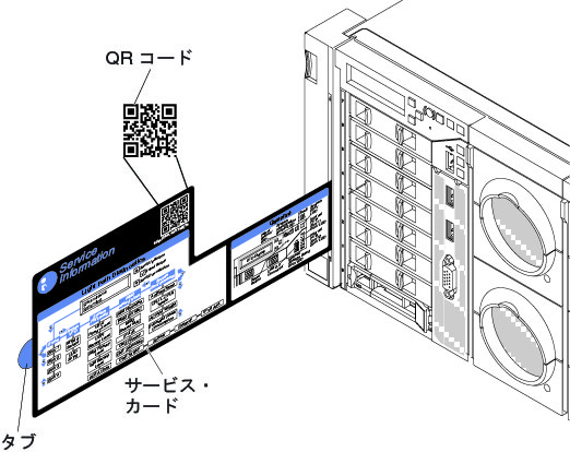
    4. Replace the IBM system Service Card with the Lenovo system Service Card that comes with the ITL kit. The following illustration shows the location of the system Service Card. To remove the system Service Card, grasp the blue tab and pull the card out.

      Illustration that shows the location of the system Service Card
    5. Attach the a new Lenovo MAC address label tag to each standard I/O book.

      Illustration that shows the location of the MAC address label
  8. Make sure that all adapters from the IBM server have been transferred to the upgraded Lenovo server and that all cables to the server are reconnected.

Update firmware and device drivers for installed components

After performing the physical conversion and updating server firmware, the service technician must also update the firmware and device drivers for all components installed in the server to their Lenovo versions. Lenovo firmware and device drivers for installed components are available at the Lenovo Data Center Support website. See the documentation for each device for additional information about how to perform the update.

Verification

After the ITL server upgrade is complete, the service technician must complete the following steps to verify operation of the Lenovo server:

  1. Make sure that the server powers up and passes UEFI initialization (see Turning on the server and Using the Setup utility).

  2. Make sure that you are able to access the IMM (see Using the integrated management module).

  3. Verify that all server vital product data (VPD) is correct (see the Integrated Management Module II User’s Guide at the Integrated Management Module II User’s Guide ).

  4. Make sure that all server firmware is updated to the latest level (see Updating the firmware).

  5. Make sure that there are no errors messages (see Error messages).

If problems are encountered following the ITL upgrade, troubleshoot the system using standard methods (see Start here). If you are unable to resolve the problem, open an online service request, go to the Service requests and PMRs website. Be prepared to provide information about any error codes and collected data.

Update customer and service records

After the ITL server upgrade is complete and verified, the service technician must contact regional support to update customer and service records as soon as possible after completing the ITL upgrade. Refer to “Servicer Only Tech Tip Document ID 5097919” for detailed contact information.

The following information is required to update the customer entitlement database:

  • The original IBM server Machine Type and serial number.

  • The upgraded Lenovo server Machine Type and serial number.

  • Include a photograph of the 11S barcode or type the serial number for each Lenovo standard I/O book that was installed.

Servicer notes
  • IBM parts are property of the customer and should be left with the customer.

  • Service technicians in each geography should report the upgrade activity, as follows:

    • For USA and China, record SC 44, AC01 against the original IBM Machine Type and serial number.

    • For EMEA, record SC 46, AC06 against the RCMS case opened for the original IBM Machine Type and serial number.

    • For Canada, record SC 33, ECA=DRA against the original IBM Machine Type and serial number.

Regional contacts:
RegionContact
NADCG_SERVICE@lenovo.com
EMEA
Note
Make sure that you copy Mark Hof (mhof@lenovo.com) on all EMEA inquires
 UKIRSteven Anderson3 (sanderson3@lenovo.com)
France/Benelux/Scandin. & FinlandRegis Clermont (rclermont@lenovo.com)
Italy/IberiaSamuel Benedetti (sbenedetti@lenovo.com)
North-West AfricaAngel Carreras Fernandez1 (afernandez1@lenovo.com)
 Russia/EECAAlexander Totikov (atotikov@lenovo.com)
 PL, CZ and SK (AR+UN)/ SEE (IN+UN)/ Greece (IN+UNMark Hof (mhof@lenovo.com) Acting
 Middle-East/PakistanAlaa Halime (ahalime@lenovo.com)
 DACH (Shared)/Israel (Andre)/ Baltics (Andre)

Uwe Nunweiler (ununweiler@lenovo.com)
Andre Reuber (areuber@lenovo.com)

 Southern Africa/Eastern Africa/Egypt and TurkeyAmir Yassien (ayassien@lenovo.com)
AP/PRCKevin Yuan (yuanxh2@lenovo.com)