Storage book
Use this information for an overview of the controls, connectors, LEDs, and components on the storage book.
The storage book houses the drives and drive backplanes, the front operator panel, the LCD system information display panel, the front I/O panel (USB 3.0/Video connectors), and the PCIe slots for the storage host bus adapters.
- Power to the storage book and the storage backplanes is provided by the standard I/O book.
- The PCIe slots on storage book are dedicated storage host bus adapters slots. Do not install any other adapters in these slots. Other adapters are not supported in these slots.
- You must power-off the server and disconnect all power cords to remove or add adapters in the PCIe slots on the storage book. The PCIe slots are not hot-swappable.
- Install internal RAID adapters and the adapter flash power modules in the storage book component.
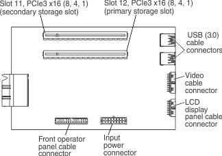
- Two x16 (8, 4, 1) PCIe Gen3 low profile slots (8 GT/s) for storage host bus adapters
- PCIe slot 12 is the primary storage slot
- PCIe slot 11 is the secondary storage slot
- One VGA connector
- One USB 2.0 connectors
- Two USB 3.0 connectors
- The front operator panel connector
- The LCD system information display panel connector
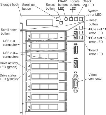
The following illustration shows the connectors, LEDs, and controls that are accessible on the storage book.
The following illustration shows the connectors on the storage book board.
- Drive status LEDs: These LEDs are on SAS or SATA hard disk drives and solid state drives. When one of these LEDs is lit, it indicates that the drive has failed. When this LED is flashing slowly (one flash per second), it indicates that the drive is being rebuilt. When the LED is flashing rapidly (three flashes per second), it indicates that the controller is identifying the drive.
Drive activity LEDs: These green LEDs are on all hot swap drives.
When this LED is flashing, it indicates that the drive is actively reading or writing data.
For SAS and SATA drives, this LED is off when the drive is powered but not active.
For NVMe (PCIe SSD) solid state drives, this LED is on solid when the drive is powered but not active.
- LCD system information display panel: This panel contains buttons that you use to navigate and select the system information that you want displayed in the LCD display area. The LCD system information display panel provides the following buttons:
- Scroll Up button: Press this button to scroll up or scroll within in the main menu to locate and select the system information that you want displayed.
- Select button: Press this button to make your selection from the menu options.
- Scroll Down button: Press this button to scroll down or scroll within the main menu to locate and select the system information that you want displayed.
- Front operator panel: This panel contains controls and LEDs that provide information about the status of the server. For more information about the controls and LEDs on the front operator panel, see Front operator panel.
- Power button/LED: Press this button to turn the server on and off manually or to wake the server from a reduced-power state. The states of the power-on LED are as follows:
- Off: Input power is not present, or the power supply or the LED itself has failed.
- Flashing rapidly (3 times per second): The server is turned off and is not ready to be turned on. The power-on button is disabled. This lasts approximately 10 seconds after input power has been applied or restored.
- Flashing slowly (once per second): The server is turned off and is ready to be turned on. You can press the power-on button to turn on the server.
- Lit: The server is turned on.
- Locate button/LED: Press this button to visually locate the server among other servers. When you press the locate button, the LED is lit and remains lit until you press it again to turn it off. This button is also used as the physical presence for the Trusted Platform Module (TPM). You can use management software, such as Lenovo XClarity Administrator software, or the IMM2 interface to light this LED remotely. This LED is controlled by the IMM2.
- Check log LED: When this LED is lit (yellow), it indicates that there are errors that require further diagnosis. Check the IMM event log for additional information. See Event logs for more information about event logs.
- System-error LED: When this yellow LED is lit, it indicates that a system error has occurred. A system-error LED is also on the rear of the server. This LED is controlled by the IMM2. Additional information can also be seen on the LCD display panel (see LCD system information display panel for more information).
- Reset button: Press this button to reset the server and run the power-on self-test (POST). You might have to use a pen or the end of a straightened paper clip to press the button. The Reset button is near the Select button on the front operator panel.
- PCIe slots 11 and 12 error LEDs: When these LEDs are lit, they indicate that an error has occurred in PCIe slots 11 and 12 on the storage book board.
- Storage board error LED: When this yellow LED is lit, it indicates that an error with the storage book board has occurred.
- USB 2.0 connector: Connect a USB device, such as a USB mouse, keyboard, or other device, to any of this connector.
- USB 3.0 connectors: Connect a USB device, such as a USB mouse, keyboard, or other device, to any of these connectors.
- Video connector: Connect a monitor to this connector. The video connectors on the front and rear of the server can be used simultaneously.
For more information about light path diagnostics, see Light path diagnostics and Light path diagnostics LEDs description.