Remove components from the left wing of riser assembly
Follow instructions in this section to remove components from the left wing of riser assembly.
About this task
Read Installation Guidelines and Safety inspection checklist to ensure that you work safely.
Power off the server and peripheral devices and disconnect the power cords and all external cables. See Power off the server.
If the node is installed in an enclosure or mounted, remove the node from the enclosure or mount. See Configuration guide.
Procedure
Remove M.2 assembly
Procedure
- Remove the M.2 cabled adapter from the riser cage.
- Disconnect the signal cable from the M.2 cabled adapter. Disconnect 2 MCIO 2 connector; then, disconnect 1 MCIO 1 connectorFigure 1. Disconnecting the signal cable
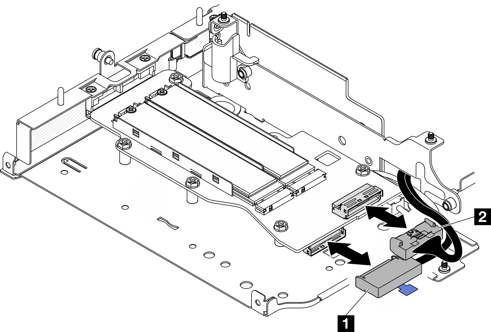
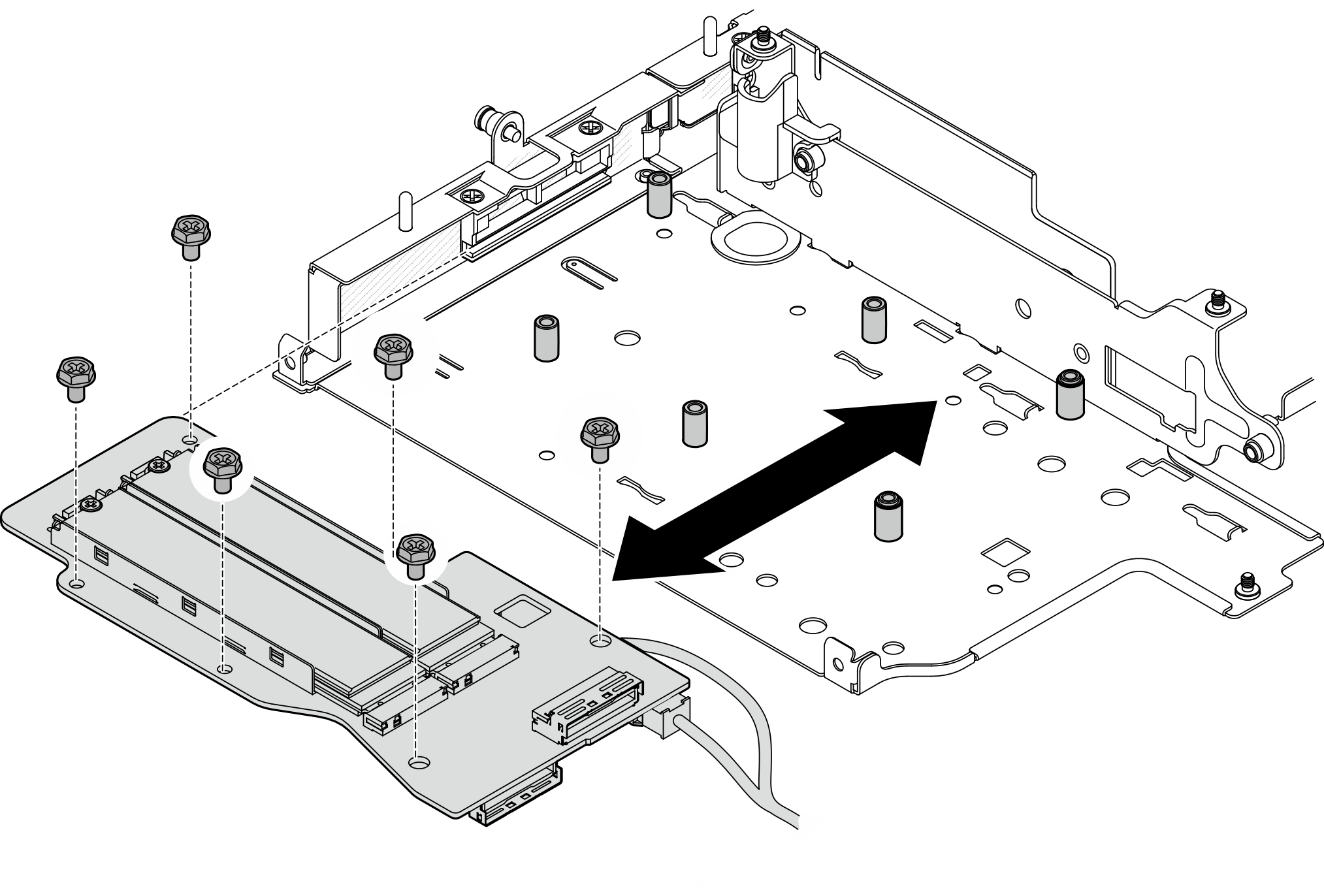
1 MCIO 1 connector 2 MCIO 2 connector - Loosen the six screws that secure the M.2 cabled adapter; then, slide the adapter outward to remove it from the riser cage.Figure 2. Removing the M.2 cabled adapter
- Disconnect the power cable from 2 Power connector 1 and 3 Power connector 2 on the M.2 cabled adapter.
Top side of M.2 cabled adapter 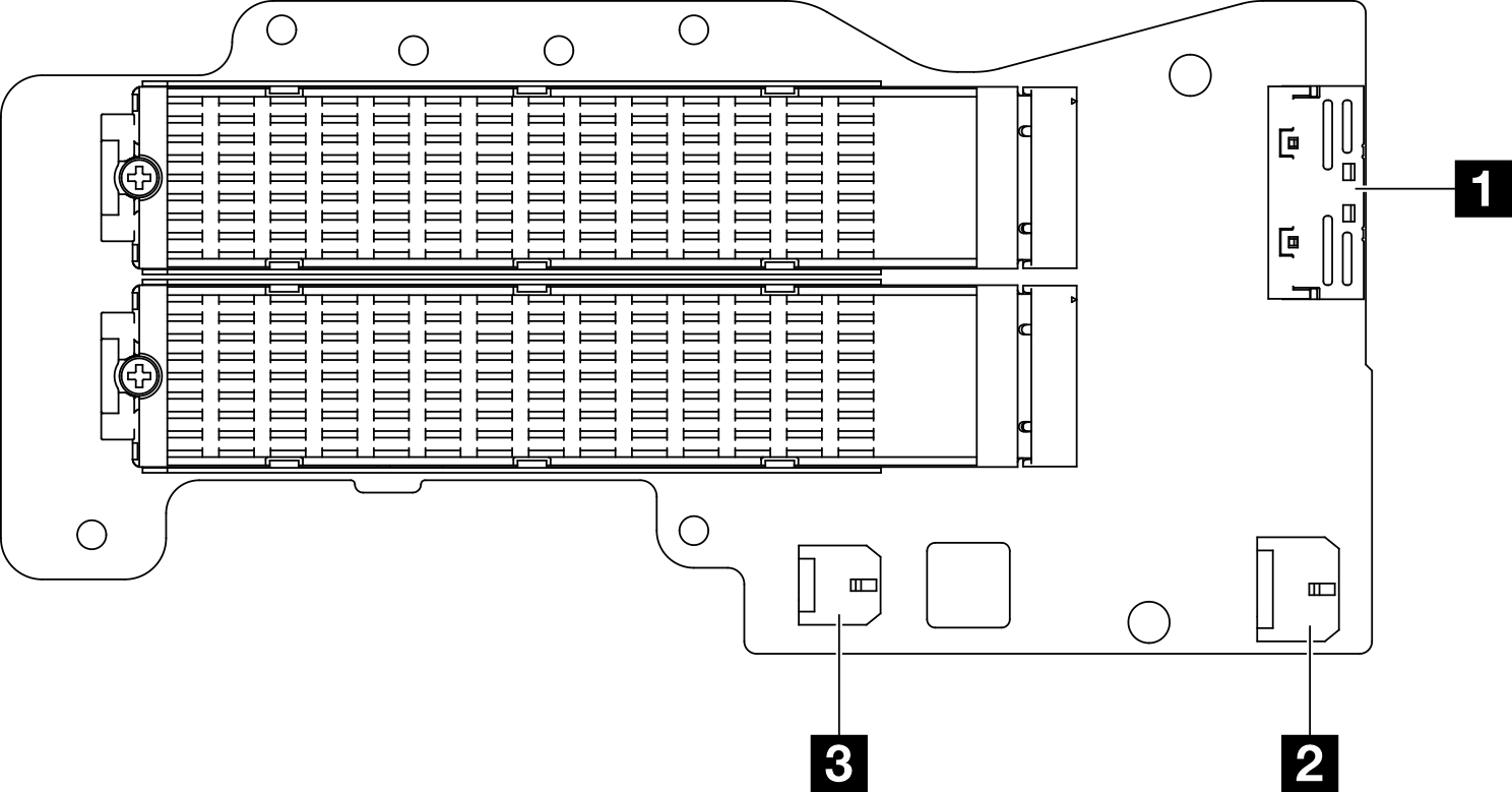
- 1 MCIO 1 connector
- 2 Power connector 1
- 3 Power connector 2
- Disconnect the signal cable from the M.2 cabled adapter. Disconnect 2 MCIO 2 connector; then, disconnect 1 MCIO 1 connector
- Remove an M.2 drive from the M.2 cabled adapter.
- Locate the M.2 drive to be removed.
Top side of M.2 cabled adapter 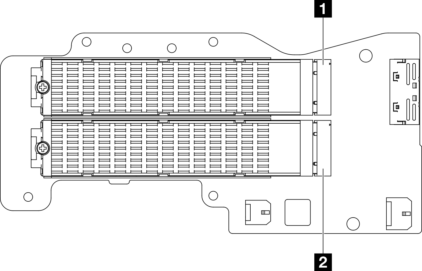
1 Slot 3 / M.2 Bay 2 2 Slot 5 / M.2 Bay 4 Bottom side of M.2 cabled adapter 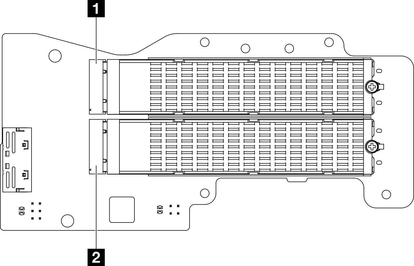
1 Slot 4 / M.2 Bay 3 2 Slot 6 / M.2 Bay 5  Loosen the screw that secures the M.2 drive.
 Pivot the rear side of the M.2 drive away from the M.2 adapter.
 Remove the M.2 drive from the slot.
Figure 3. Removing an M.2 drive Note
NoteIf necessary, repeat this procedure to other M.2 drives to be removed.
- Locate the M.2 drive to be removed.
After this task is completed
Install a replacement unit. See Install components to the left wing of riser assembly.
If you are instructed to return the component or optional device, follow all packaging instructions, and use any packaging materials for shipping that are supplied to you.
Remove PCIe assembly
- Remove the PCIe adapter from the riser cage.
- Loosen the screw that secures the holder, and remove the holder.
- Loosen the screw that secures the PCIe adapter.
- Slide the PCIe adapter outward to remove it.
Note- If no PCIe adapter is to be installed to this slot, insert the PCIe filler and secure it with one screw.
If no PCIe adapter is to be installed to this slot, to save the holder for future use, insert the holder to the slot on riser cage, and secure the holder with one screw.
Figure 4. Removing the PCIe adapter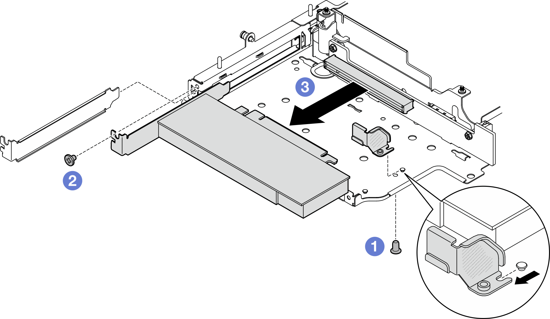
- Remove the PCIe cabled riser card from the riser cage.
- Remove the riser card.Figure 5. Removing the riser card
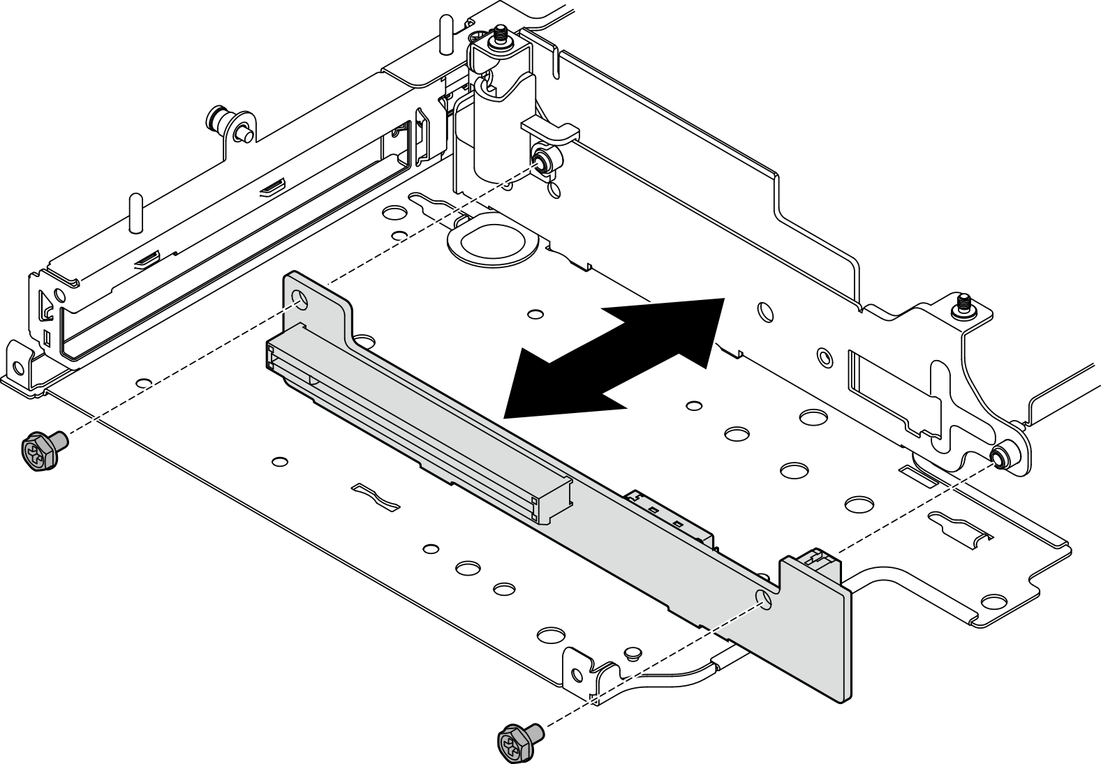
- Remove the riser card.
After this task is completed
Install a replacement unit. See Install components to the left wing of riser assembly.
If you are instructed to return the component or optional device, follow all packaging instructions, and use any packaging materials for shipping that are supplied to you.
Remove drive backplanes
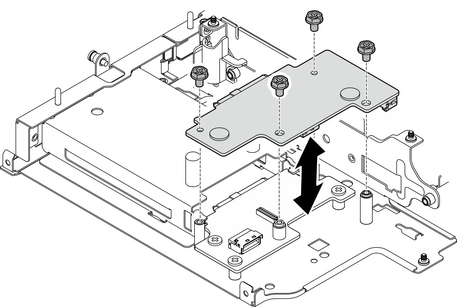
- Loosen the four screws that secure Backplane 2; then, lift Backplane 2 to remove it.Figure 6. Removing Backplane 2
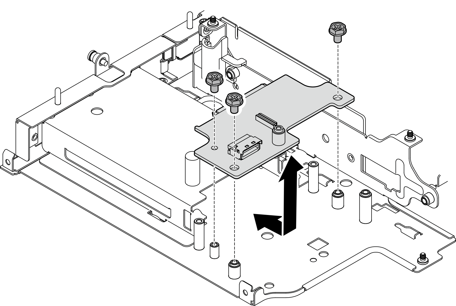
- Loosen the three screws that secure Backplane 1; then, lift Backplane 1 to remove it.Figure 7. Removing Backplane 1
After this task is completed
Install a replacement unit. See Install components to the left wing of riser assembly.
If you are instructed to return the component or optional device, follow all packaging instructions, and use any packaging materials for shipping that are supplied to you.
Remove PCIe assembly + geotracking module
- Remove the geotracking module.
- Push the latch to disengage the geotracking module.
- Lift the geotracking module from the cage.
Figure 8. Removing the geotracking module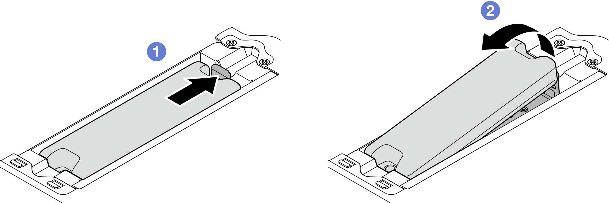
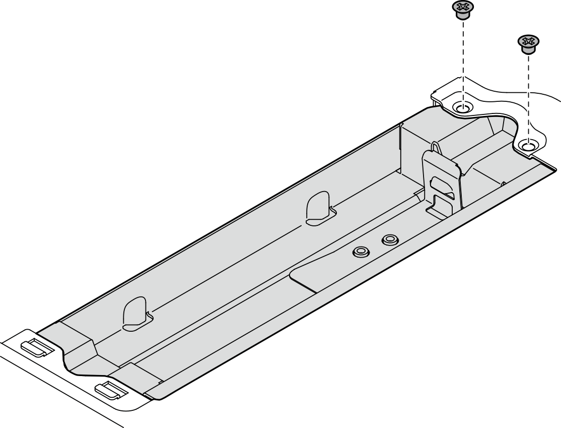
- Remove the geotracking module cage.
- Loosen the two screws that secure the geotracking module cage.Figure 9. Removing the geotracking module cage
- Push the geotracking module cage as shown to disengage the tabs from the slots.
- Slide the geotracking module cage outward to remove it from the riser cage.Figure 10. Removing the geotracking module cage

- Loosen the two screws that secure the geotracking module cage.
- Remove the PCIe adapter from the riser cage.
- Loosen the screw that secures the PCIe adapter.
- Slide the PCIe adapter outward to remove it.
NoteIf no PCIe adapter is to be installed to this slot, insert the PCIe filler and secure it with one screw.Figure 11. Removing the PCIe adapter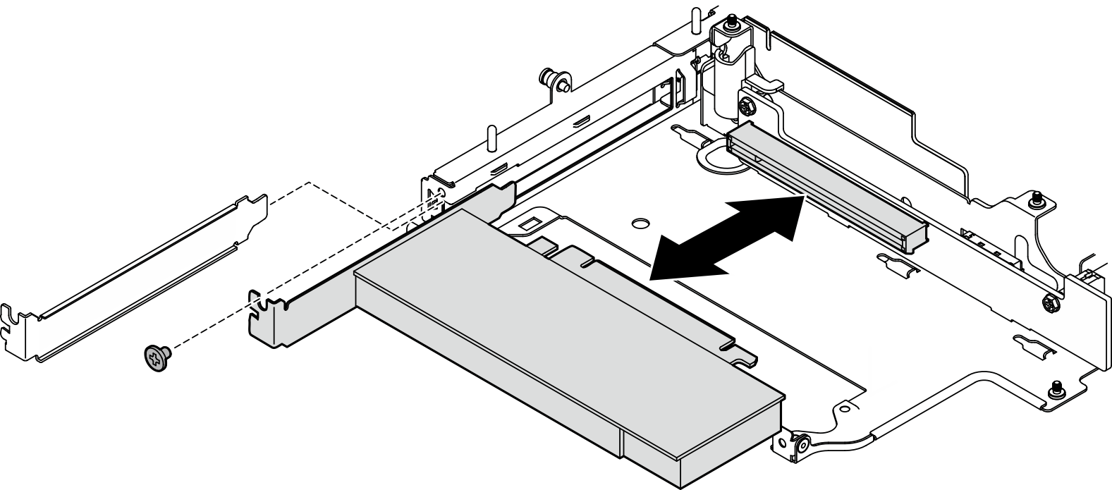
- Remove the PCIe cabled riser card from the riser cage.
- Remove the riser card.Figure 12. Removing the riser card
- Remove the riser card.
After this task is completed
Install a replacement unit. See Install components to the left wing of riser assembly.
If you are instructed to return the component or optional device, follow all packaging instructions, and use any packaging materials for shipping that are supplied to you.
Demo Video