Install the riser assembly to the node
Follow instructions in this section to install the riser assembly to the node.
About this task
Read Installation Guidelines and Safety inspection checklist to ensure that you work safely.
Power off the server and peripheral devices and disconnect the power cords and all external cables. See Power off the server.
Touch the static-protective package that contains the component to any unpainted metal surface on the server; then, remove it from the package and place it on a static-protective surface.
Proceed to the section corresponding to the selected configuration on the left wing of riser assembly:
PCIe assembly configuration
Procedure
- Connect the riser assembly cables.NoteIf necessary, remove the memory modules from DIMM slot 3 and 4 for easier operation. See
Remove a memory module. 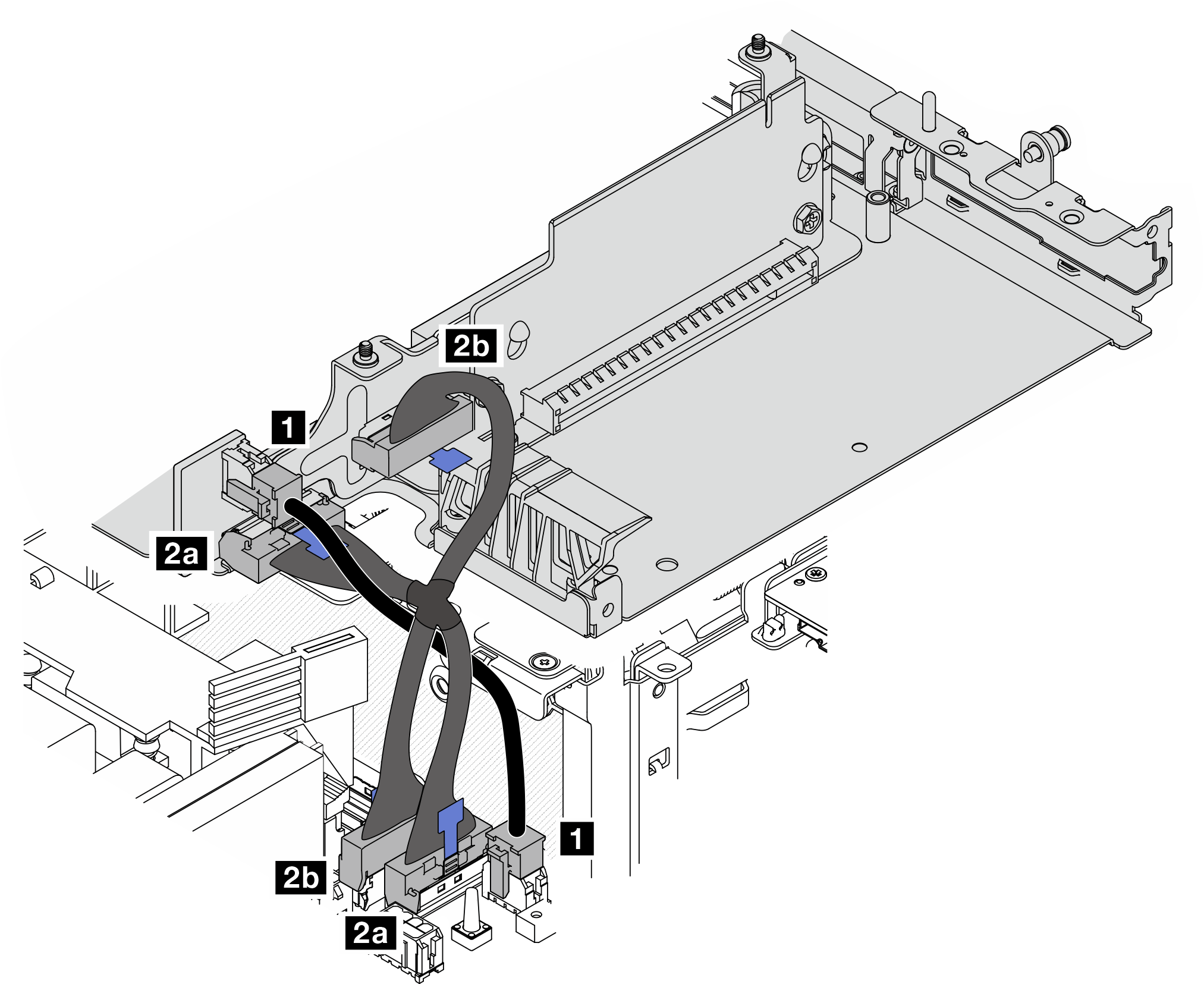
Cable From: PCIe cabled riser card To: System board Cable length 1 Power connector M.2 cabled adapter / PCIe cabled riser card power connector 100mm 2 2a MCIO 1 connector
2b MCIO 2 connector
2a MCIO 1 connector
2b MCIO 2 connector
140/120mm NoteMake sure to route the cables as shown in the illustration.- Connect 1 the power cable to the system board.
- Connect 2a the MCIO2 branch of riser card signal cable to the system board.
- Connect 2b the MCIO1 branch of riser card signal cable to the system board.
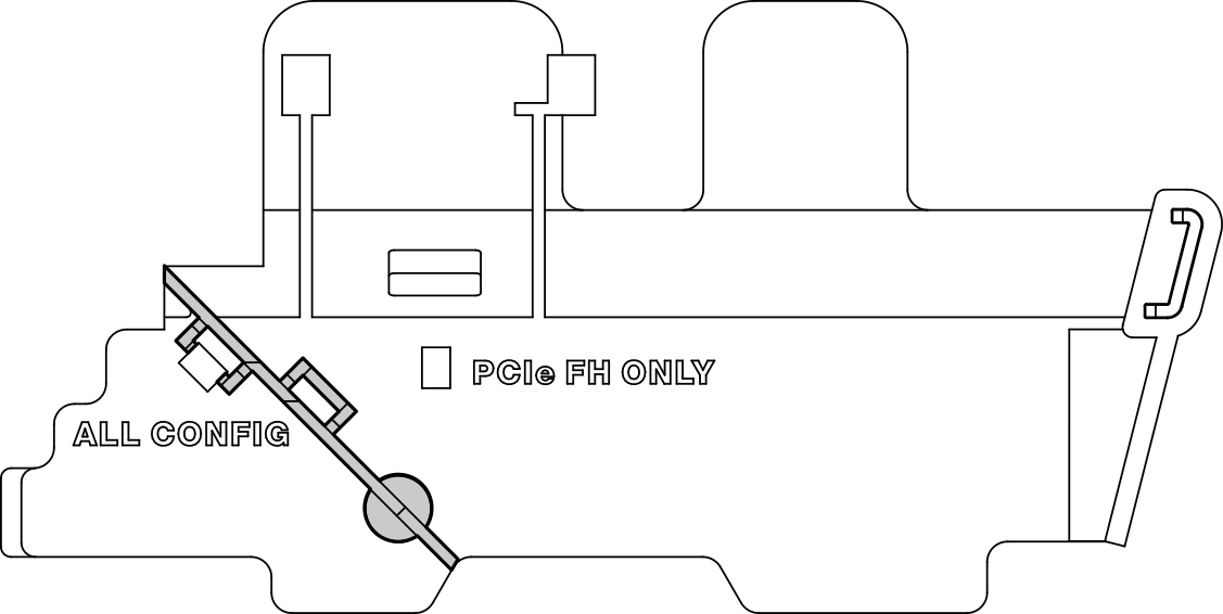
- Reinstall the processor air baffle. See Install the processor air baffle and air flow sensor board.NoteMake sure to adjust the processor air baffle according to the configuration.
For the configuration with full-height PCIe adapter For the configuration without full-height PCIe adapter 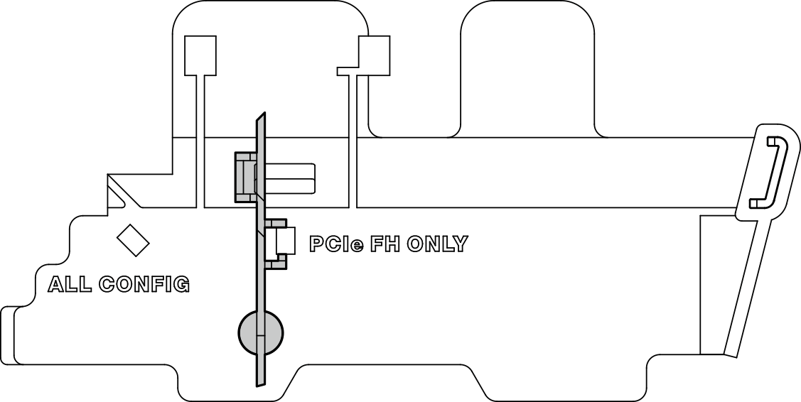
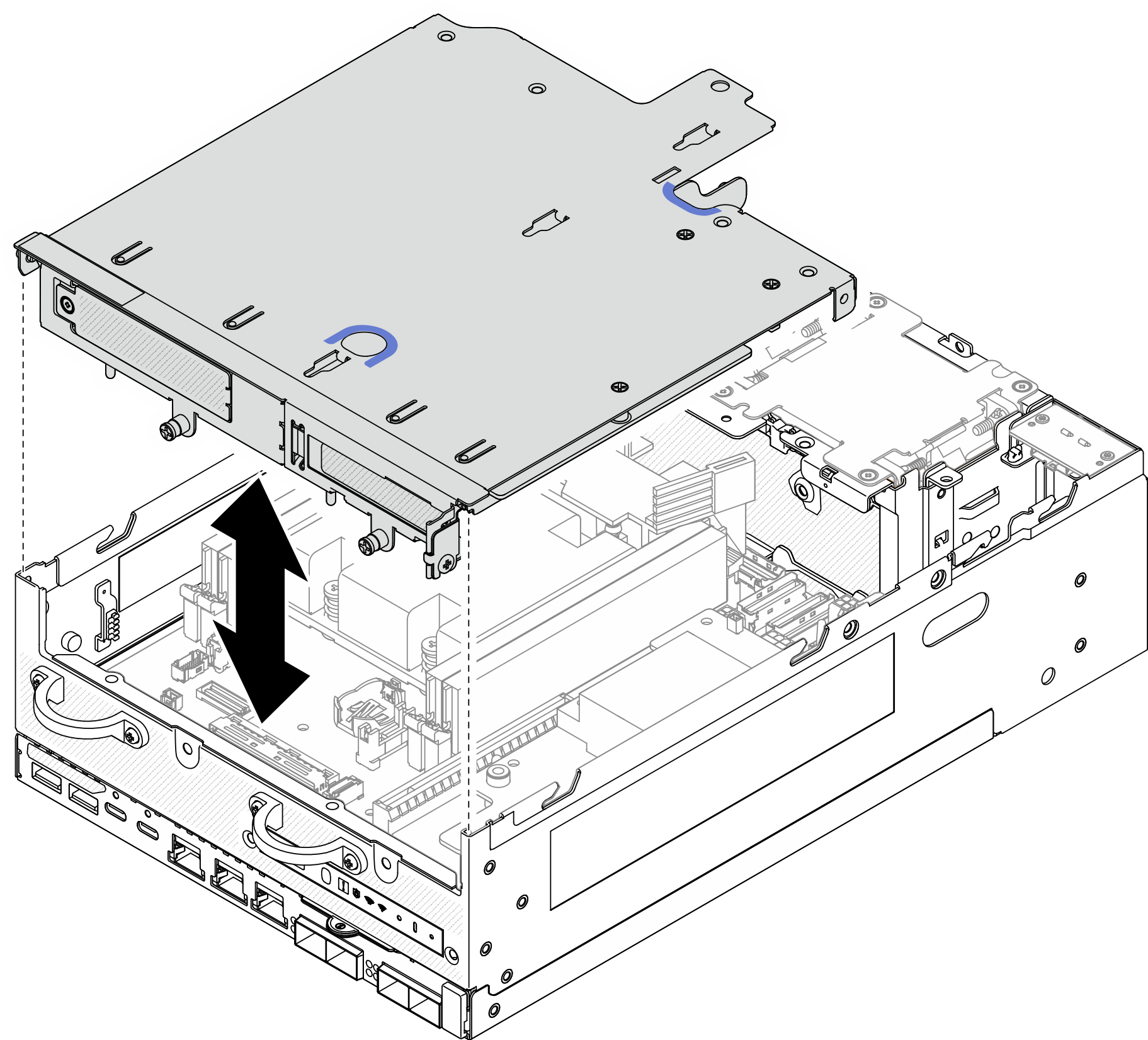
- Align the front of the riser assembly with the edge of the chassis; then, lower the riser assembly to the node.Figure 1. Lowering the riser assembly
- Secure the riser assembly to the node.
 Tighten the three captive screws on the top of the riser assembly.
 Tighten the three screws on both sides of the node.
 Tighten the two thumbscrews in the front of the riser assembly.
Figure 2. Securing the riser assembly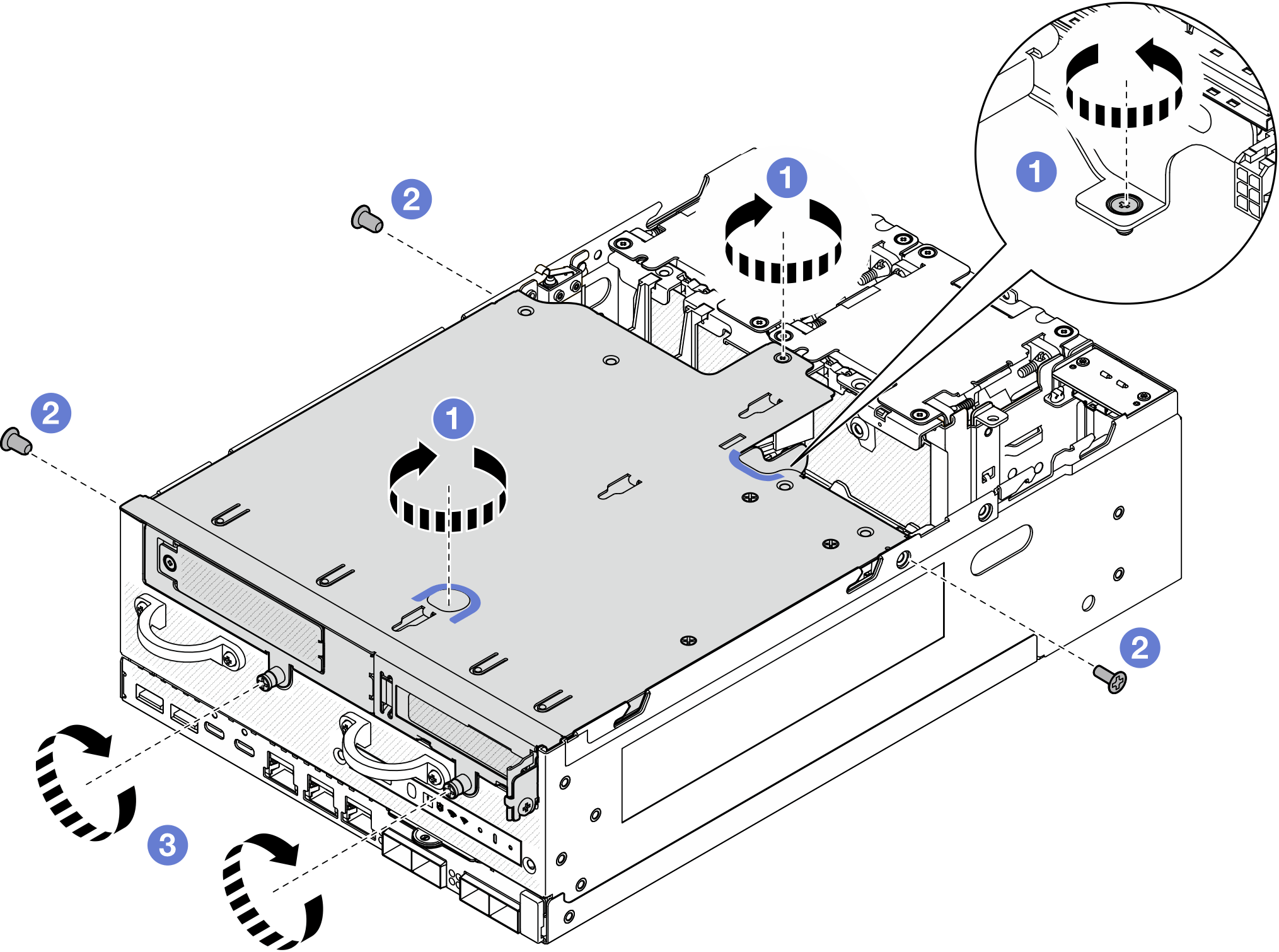
- Bundle the riser assembly cables together with a velcro strap; then, push the bundled cables toward the riser card.NoteTo make sure adequate system cooling, the cables should be routed away from the space for PMB air baffle.Figure 3. Cable routing for riser assembly
After this task is completed
Complete the parts replacement. See Complete the parts replacement.
Demo Video
7mm drive backplane configuration
Procedure
- Connect the riser assembly cables.NoteIf necessary, remove the memory modules from DIMM slot 3 and 4 for easier operation. See
Remove a memory module. 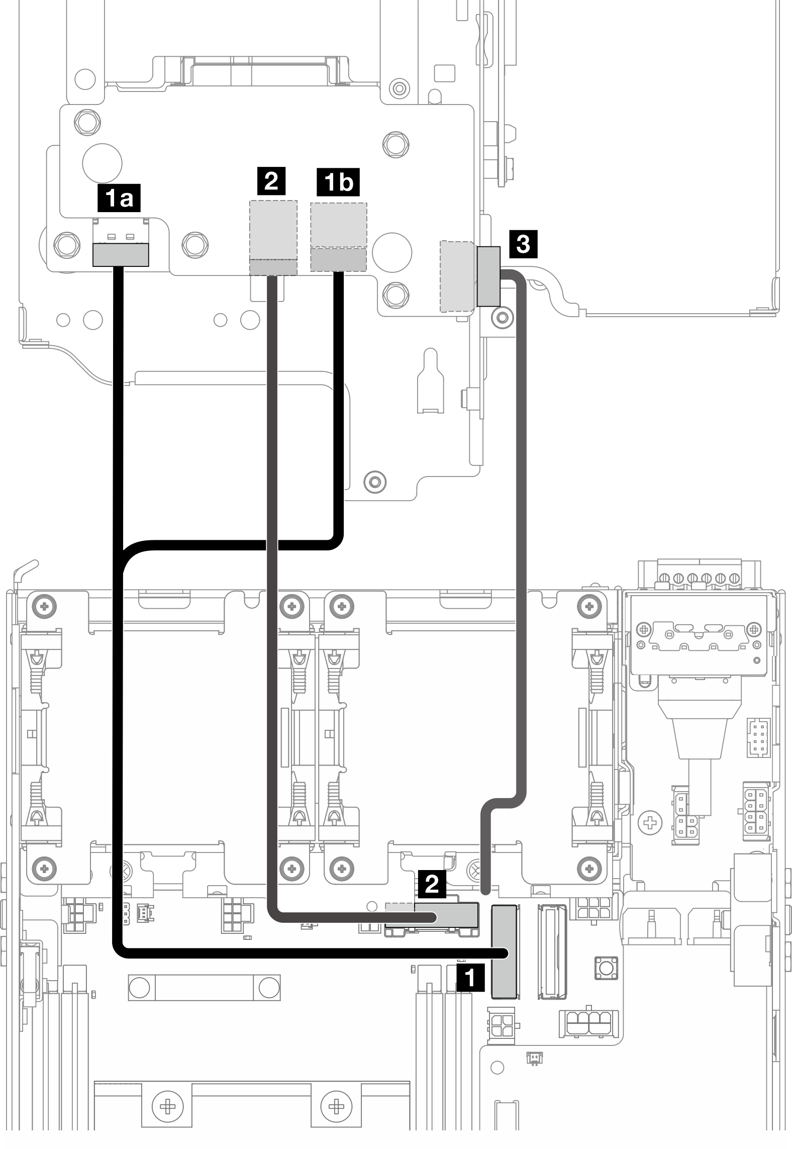
- Connect the NVMe signal cable to 1 PCIe Gen 4 MCIO 1 connector on the system board.
- Connect the SATA signal cable to 2 PCIe Gen 3 / SATA connector on the system board.
- Connect the power cable to 3 Backplane power connector on Backplane 1.
- Reinstall the processor air baffle. See Install the processor air baffle and air flow sensor board.NoteMake sure to adjust the processor air baffle according to the configuration.
For the configuration with full-height PCIe adapter For the configuration without full-height PCIe adapter - Align the front of the riser assembly with the edge of the chassis; then, lower the riser assembly to the node.Figure 4. Lowering the riser assembly
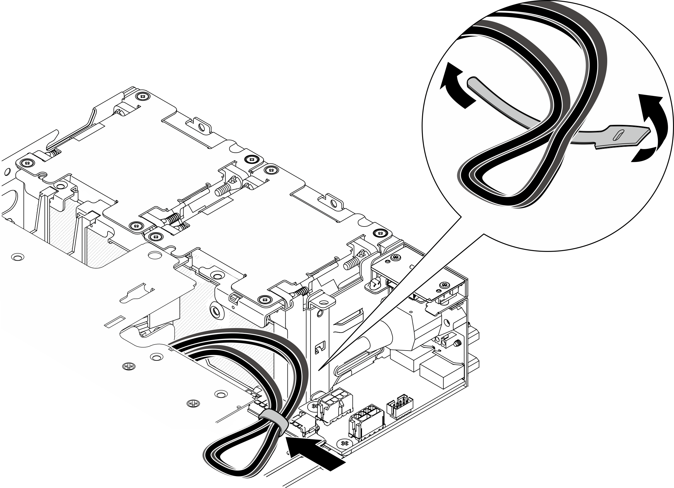
- Route the cables between the riser cage and the processor air baffle.
- Push the cables toward the riser cage until the cables are seated in the notch of riser cage.
- Push the rubber part of processor air baffle to bend it until it is against the cables.
Figure 5. Routing the cables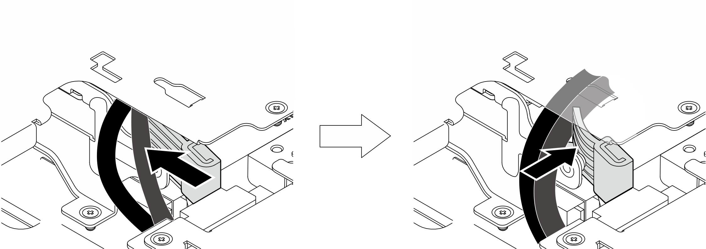
- Secure the riser assembly to the node.
- Tighten the three captive screws on the top of the riser assembly.
- Tighten the three screws on both sides of the node.
- Tighten the two thumbscrews in the front of the riser assembly.
Figure 6. Securing the riser assembly
After this task is completed
Complete the parts replacement. See Complete the parts replacement.
Demo Video
M.2 assembly configuration
Procedure
- Connect the riser assembly cables.NoteIf necessary, remove the memory modules from DIMM slot 3 and 4 for easier operation. See
Remove a memory module. 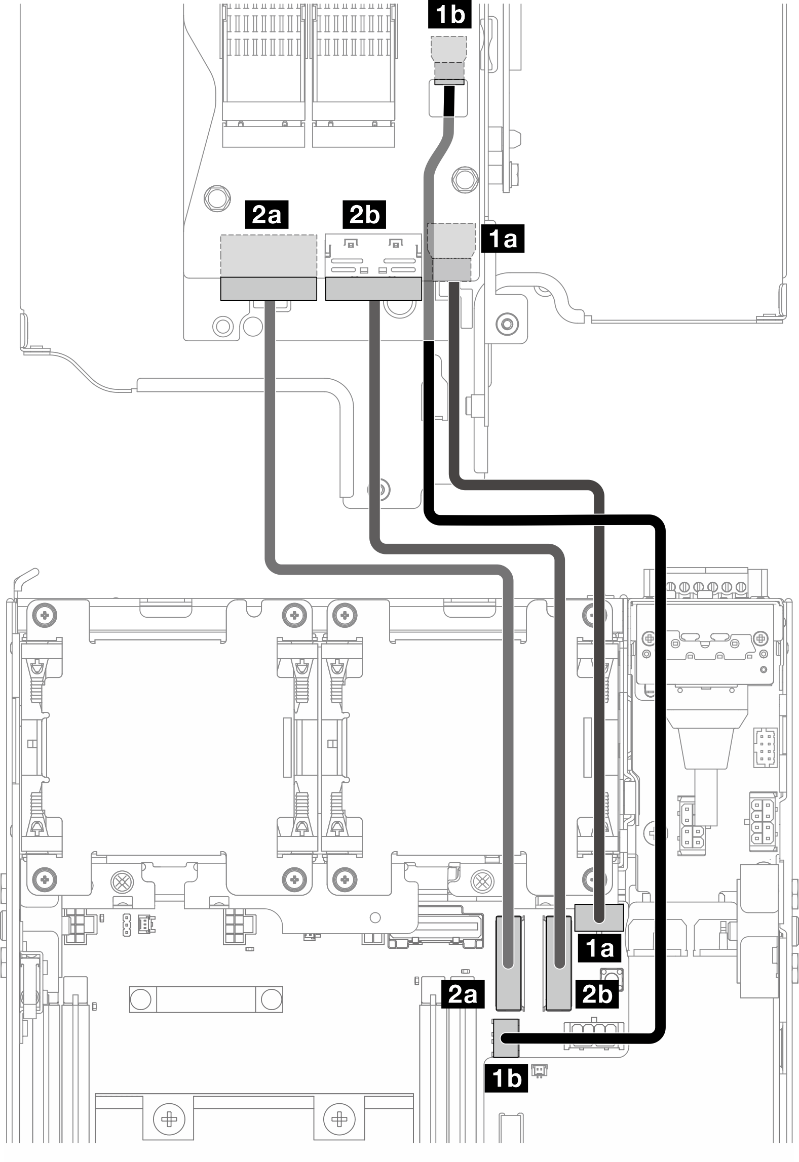
Cable From: M.2 cabled adapter To: System board Cable length 1 1a Power connector 1
1b Power connector 2
1a M.2 cabled adapter / PCIe cabled riser card power connector
1b M.2 cabled adapter power connector
170/200mm 2 2a MCIO 1 connector
2b MCIO 2 connector
2a PCIe Gen 4 MCIO 1 connector
2b PCIe Gen 4 MCIO 2 connector
150mm - Connect the power cable to 1a M.2 cabled adapter / PCIe cabled riser card power connector and 1b M.2 cabled adapter power connector on the system board.
- Connect the signal cable to 2a PCIe Gen 4 MCIO 1 connector on the system board.
- Connect the signal cable to 2b PCIe Gen 4 MCIO 2 connector on the system board.
- Reinstall the processor air baffle. See Install the processor air baffle and air flow sensor board.NoteMake sure to adjust the processor air baffle according to the configuration.
For the configuration with full-height PCIe adapter For the configuration without full-height PCIe adapter - Align the front of the riser assembly with the edge of the chassis; then, lower the riser assembly to the node.Figure 7. Lowering the riser assembly
- Route the cables between the riser cage and the processor air baffle.
- Push the cables toward the riser cage until the cables are seated in the notch of riser cage.
- Push the rubber part of processor air baffle to bend it until it is against the cables.
Figure 8. Routing the cables - Secure the riser assembly to the node.
- Tighten the three captive screws on the top of the riser assembly.
- Tighten the three screws on both sides of the node.
- Tighten the two thumbscrews in the front of the riser assembly.
Figure 9. Securing the riser assembly - Bundle the riser assembly cables together with a velcro strap; then, push the bundled cables toward the riser card.NoteTo make sure adequate system cooling, the cables should be routed away from the space for PMB air baffle.Figure 10. Cable routing for riser assembly
After this task is completed
Complete the parts replacement. See Complete the parts replacement.
Demo Video