Internal cable routing and connectors
This section provides information about routing the cables when you install some components in the server.
- Turn off the server and peripheral devices and disconnect the power cords and all external cables before routing the cables.
- Always match the numbers on the printed circuit boards and the numbers on the cables to connect the cables.
For more information about the requirements for cables and connecting devices, see the documentation that comes with these devices.
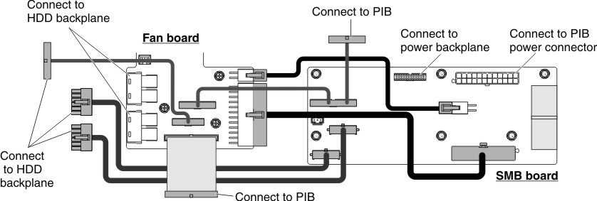
The following illustration displays the cabling information on the fan board:
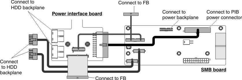
The following illustration displays the cabling information on the power interface board:
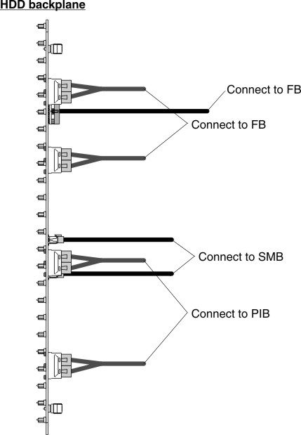
The following illustration displays the cabling information on the hard disk drive backplane:
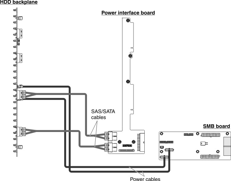
The following illustration displays the cabling information on the hard disk drive backplane and the power interface board:
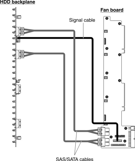
The following illustration displays the cabling information on the hard disk drive backplane and the fan board:
The following illustration displays the cabling information on the front I/O and the fan board:
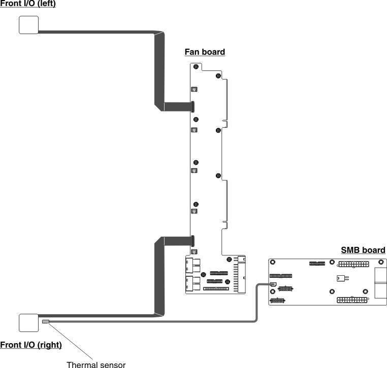
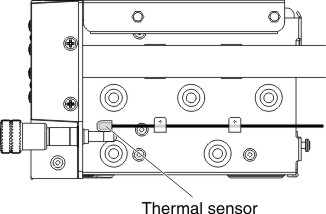
The following illustration displays the location of the thermal sensor.