48U Advanced Rack Extension Kit 설치
이 항목에서 48U Advanced Rack Extension Kit 설치 방법을 알아보십시오.
주
각 랙 확장 키트 유닛에는 랙의 각 측면에 0U PDU 최대 2개, 또는 0U PDU 1개와 매니폴드 1개를 위한 추가 용량이 제공됩니다.
랙 캐비넷마다 랙 확장 키트 유닛을 최대 2개 지원합니다(앞면 1개 및 뒷면 1개).
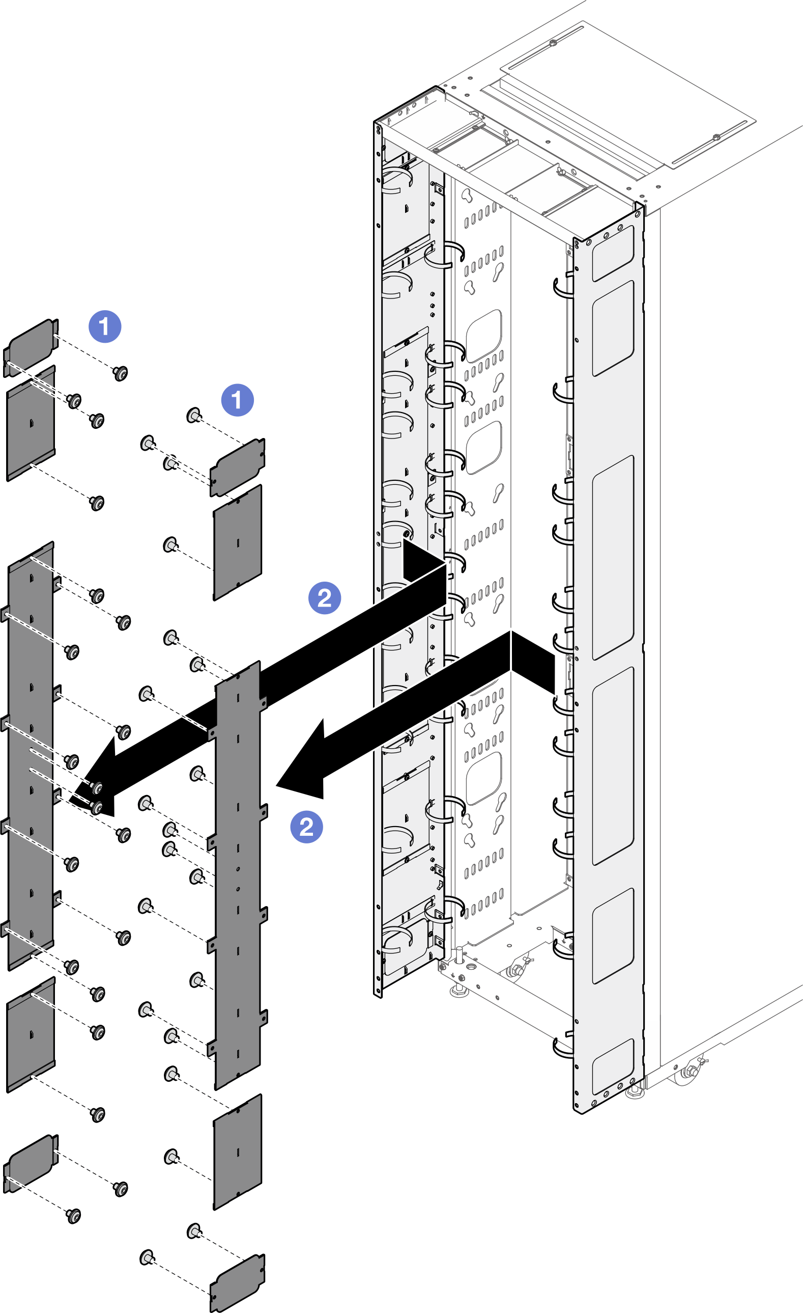
인접한 캐비넷 중 하나만 확장하여 설치할 예정이면서 베잉 키트를 설치할 계획이 있는 경우에는 먼저 베잉 키트를 설치해야 합니다(베잉 키트 설치 참조). 그런 다음 이 절차를 준비하기 위해 랙 확장 키트로 설치할 캐비넷의 상부 및 하부에서 나사 2개를 제거하고 2(으)로 이동합니다.
그림 1. 확장 설치 준비를 위해 나사 제거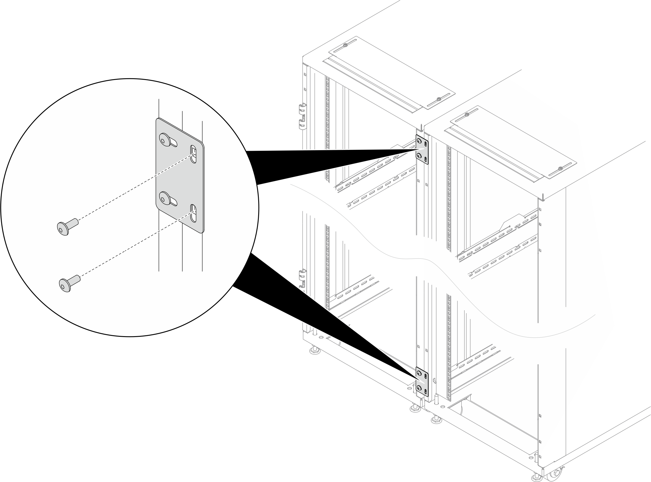
- 필수 도구
- 포장을 열기 위한 플라스틱 칼날/가위가 있는 도구 1개
- 확장 패널을 랙 측면에 맞추기 위한 고무 망치 1개
- M6 나사를 조이기 위한 3번 Phillips 비트가 있는 드라이버 1개(다음 글머리 기호에 9)
- M6 나사를 조이기 위해 육각 비트를 10mm 고정하는 너트 드라이버 1개(다음 글머리 기호에 9)
- M4 나사를 조이기 위한 2.5mm 육각 비트 소켓 1개(다음 글머리 기호에 13)
- M5 나사를 조이기 위한 3mm 육각 비트 소켓 1개(PDU/매니폴드 브래킷, 확장 패널의 열림 덮개)
- M6 나사를 조이기 위한 4mm 육각 비트 소켓 1개(다음 글머리 기호에 3 및 12)
- 확장 키트에는 다음 구성 요소가 들어 있는 기타 품목 가방이 함께 제공됩니다.그림 2. 부품
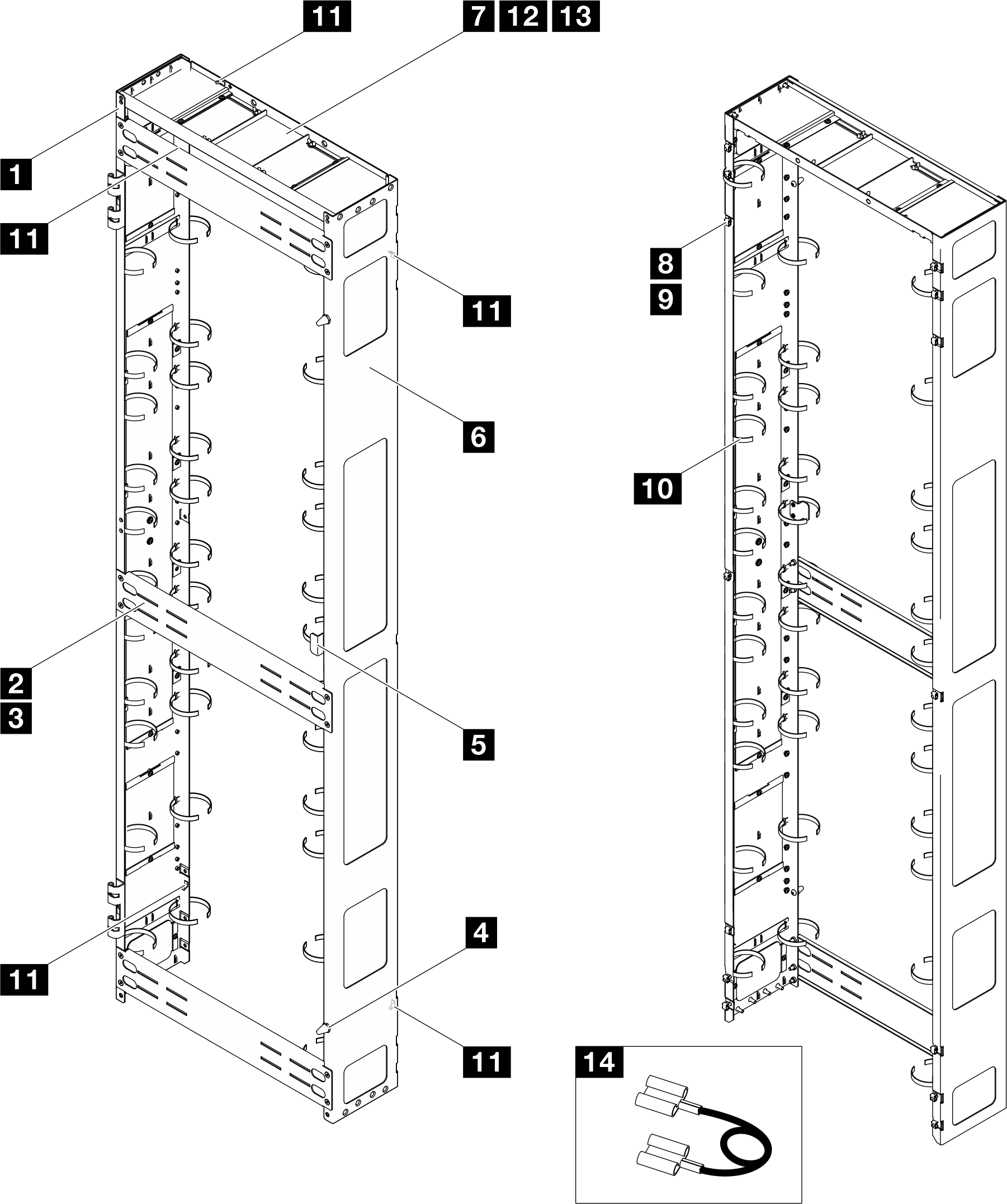
번호 설명 수량 번호 설명 수량 1 왼쪽 확장 패널 1 8 M6 케이지 너트 14 2 지지 브래킷 3 9 M6 x 16mm 육각 머리 플랜지 나사 14 3 M6 x 12mm 접시 머리 나사 12 10 케이블 스트랩 모듈 123 2 4 도어스토퍼 2 11 접지판 5 5 도어 래치 1 12 M6 x 16mm 접시 머리 나사 2 6 오른쪽 확장 패널 1 13 M4 x 6mm 일자형 소켓 캡 나사 4 7 확장 윗면 덮개 1 14 접지선 4 3 - 1 케이블 스트랩은 탈착 가능하며, 필요한 경우 확장 패널에서 스트랩을 제거하십시오.
- 2 케이블 스트랩은 2개 이상의 스트랩을 함께 연결하여 연장 가능합니다.
- 3 배송하기 전에 케이블 스트랩을 사용하여 PDU와 매니폴드를 고정하십시오.
- 4 접지선의 한쪽 끝을 확장 패널의 접지판에 연결하고 다른 쪽 끝을 랙의 가장 가까운 접지판에 연결합니다.
그림 3. 육각 앨런 렌치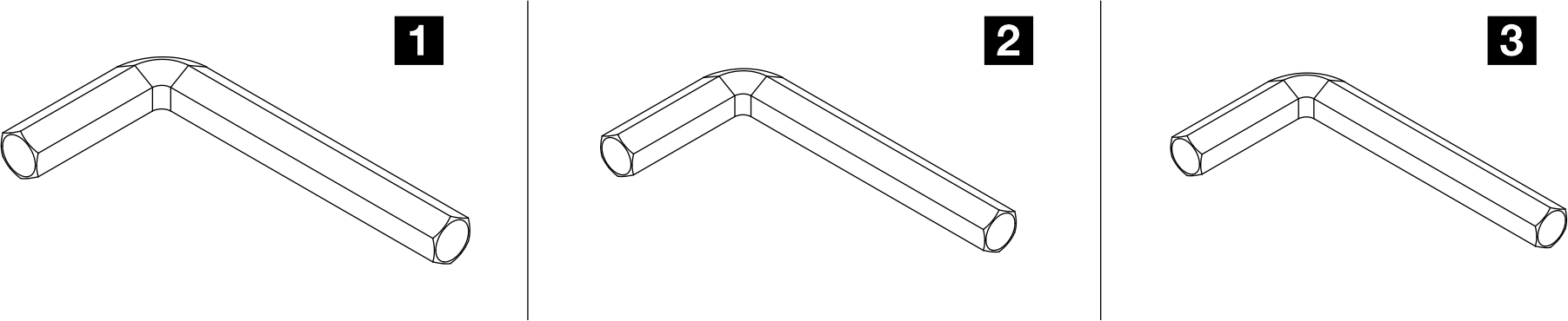
번호 설명 1 육각 앨런 렌치, 4mm 2 육각 앨런 렌치, 3mm 3 육각 앨런 렌치, 2.5mm
절차
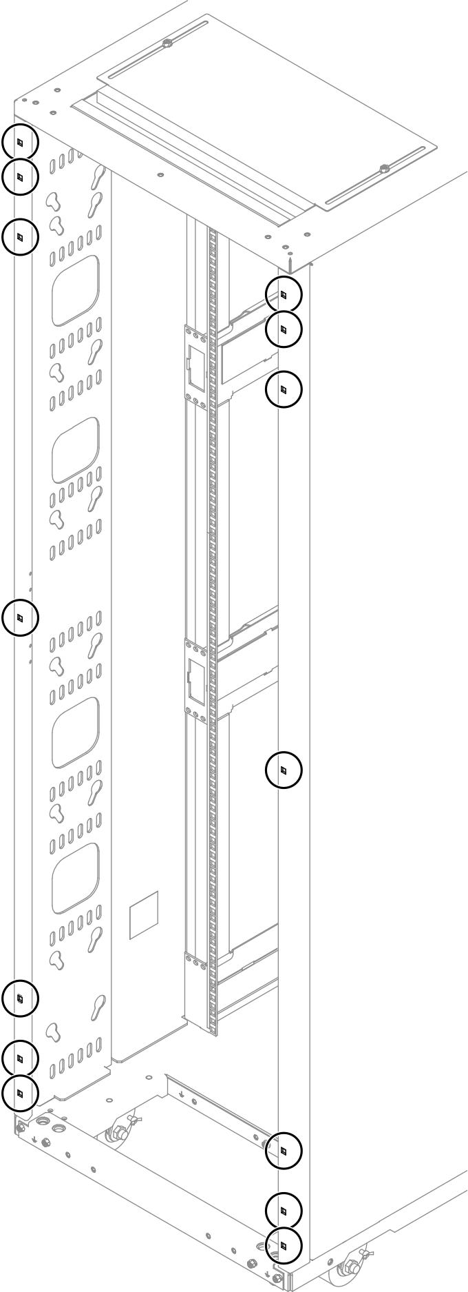
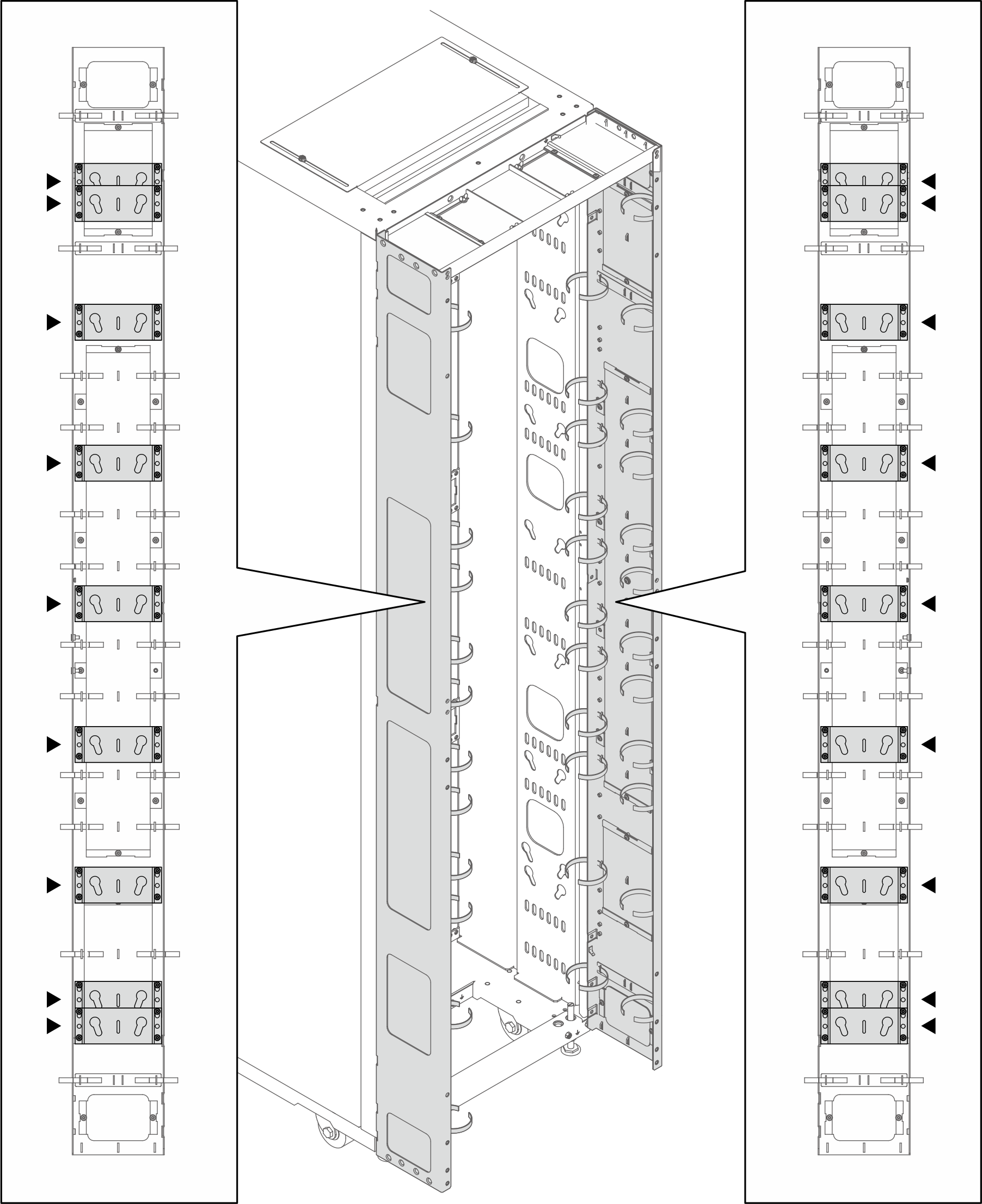
- 케이지 너트 삽입 도구 또는 일자 드라이버를 사용하여 M6 케이지 너트 14개를 랙 프레임에 설치합니다.그림 4. 케이지 너트 설치 위치
 케이지 너트 삽입 도구 사용그림 5. 케이지 너트 삽입 도구로 케이지 너트 설치
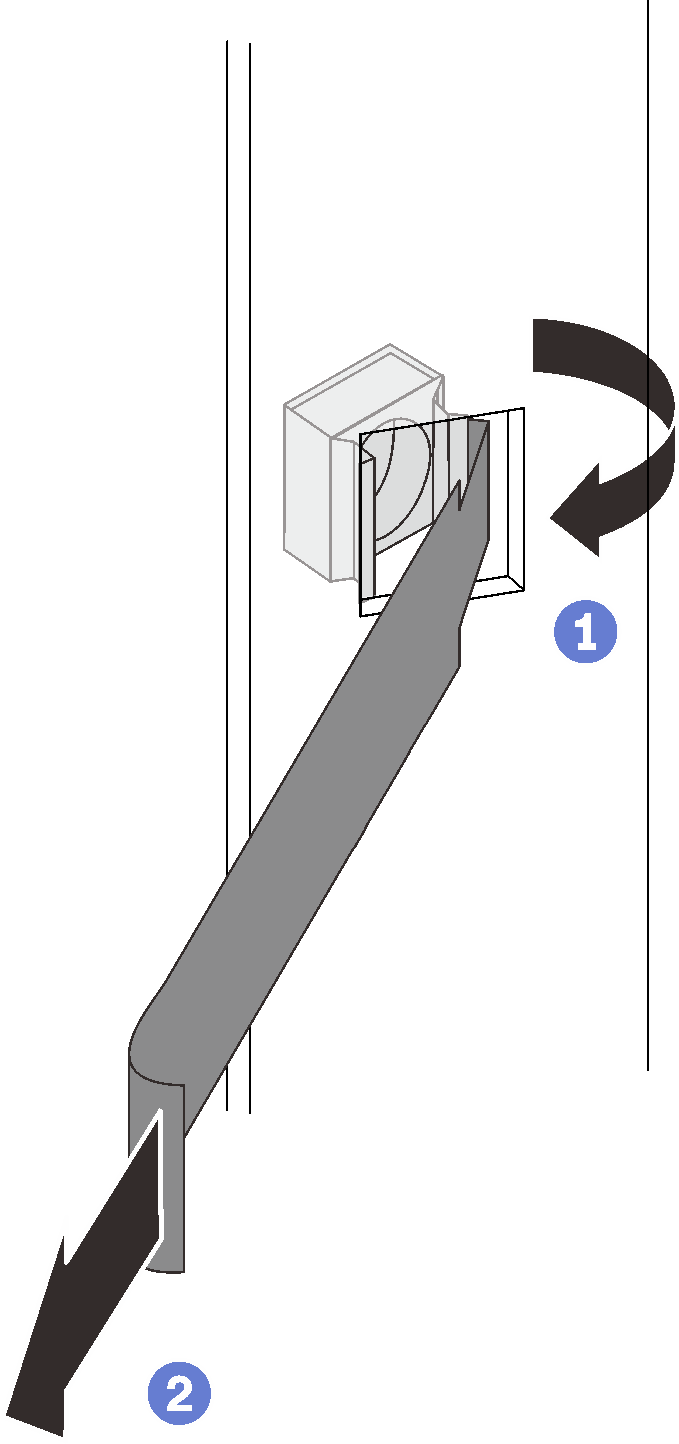
 케이지 너트의 한쪽 가장자리를 해당 마운팅 플랜지 구멍에 삽입하고 삽입 도구로 플랜지 구멍을 통해 다른 가장자리를 걸어줍니다.
 삽입 도구를 돌리고 당겨 너트의 다른 가장자리가 플랜지 구멍에 들어가도록 하여 너트를 고정합니다.
일자 드라이버 사용그림 6. 일자 드라이버로 케이지 너트 설치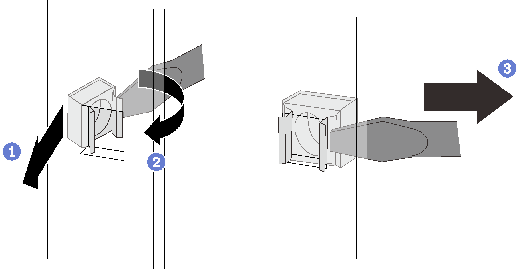
- 케이지 너트의 한쪽 가장자리를 해당 마운팅 플랜지 구멍에 삽입합니다.
- 일자 드라이버로 너트의 다른 가장자리를 눌러 압축시키고 너트 가장자리가 구멍에 들어갈 때까지 드라이버를 플랜지 구멍 방향으로 돌립니다.
 드라이버를 놓아 마운팅 플랜지 구멍에 너트를 고정합니다.
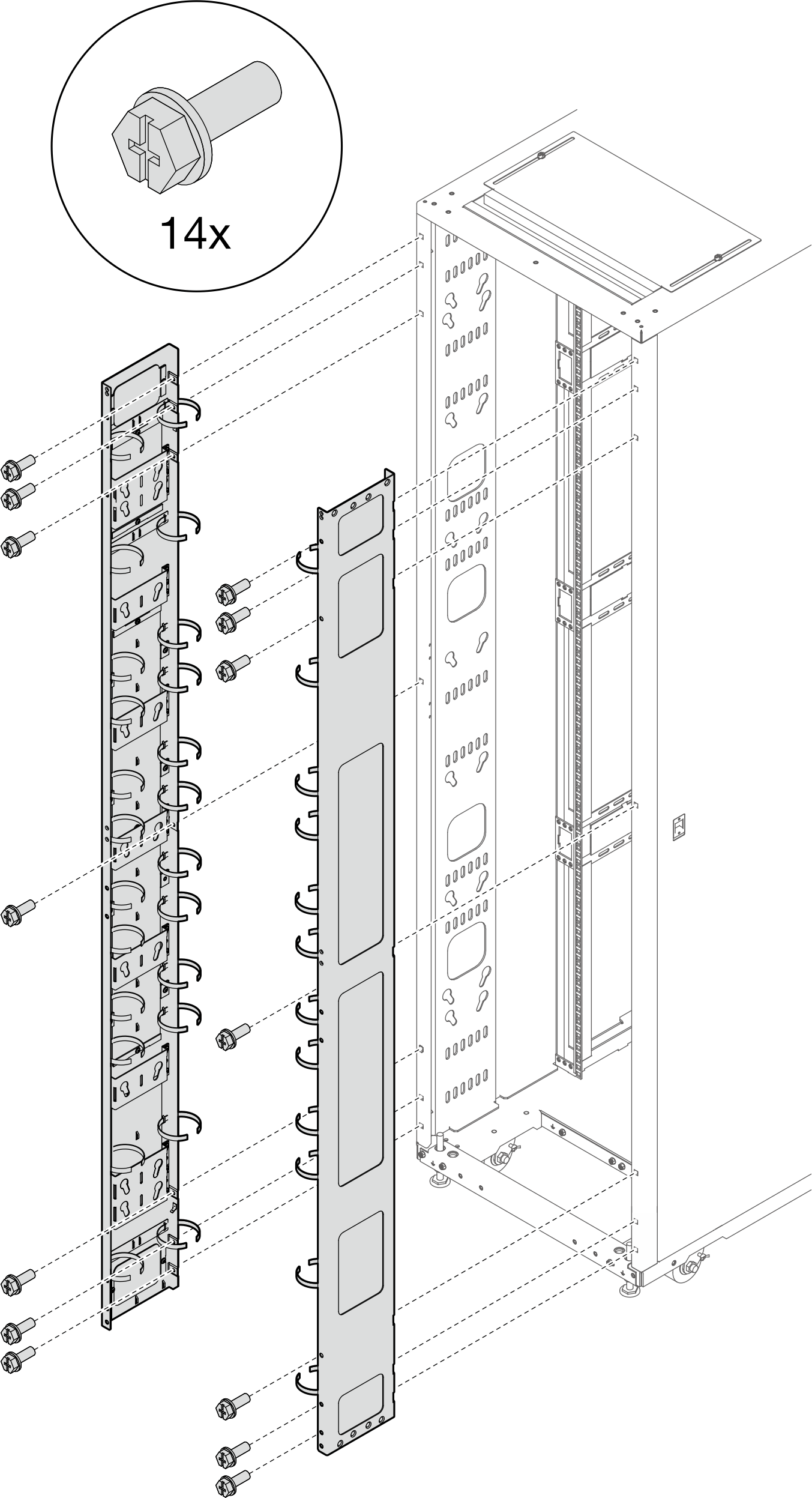
- 나사 14개를 조여 확장 패널 2개를 랙에 고정하십시오.주이전에 베잉 키트를 설치한 경우 먼저 캐비넷의 상단과 하단에서 나사 2개를 제거해야 합니다. 그런 다음 패널과 베잉 키트를 통해 나사를 고정합니다.그림 7. 확장 패널 설치
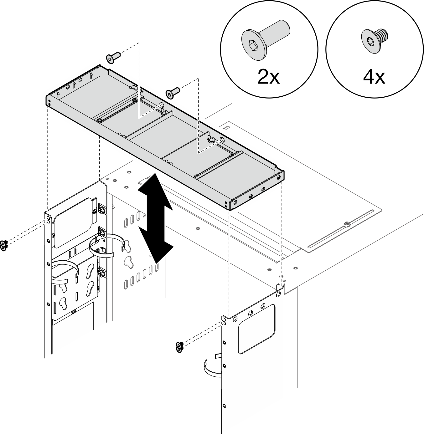
- 확장 윗면 덮개를 확장 패널의 나사 구멍에 맞추고 나사 6개로 고정합니다.그림 8. 확장 윗면 덮개 설치
- 요구 사항에 따라 확장 패널에서 필러를 제거하여 케이블을 배선합니다.그림 9. 필러 제거
- 필러를 확장 패널에 고정하는 나사를 풀어줍니다.
- 필러를 제거합니다.
- 확장 패널에 0U PDU를 설치할 계획이 있는 경우 다음 단계를 완료하십시오.요구 사항에 따라 해당 설치 절차를 선택하십시오.
- 키홀 슬롯 2개가 있는 브래킷(PDU 최대 2개, 또는 PDU 1개와 매니폴드 1개)주
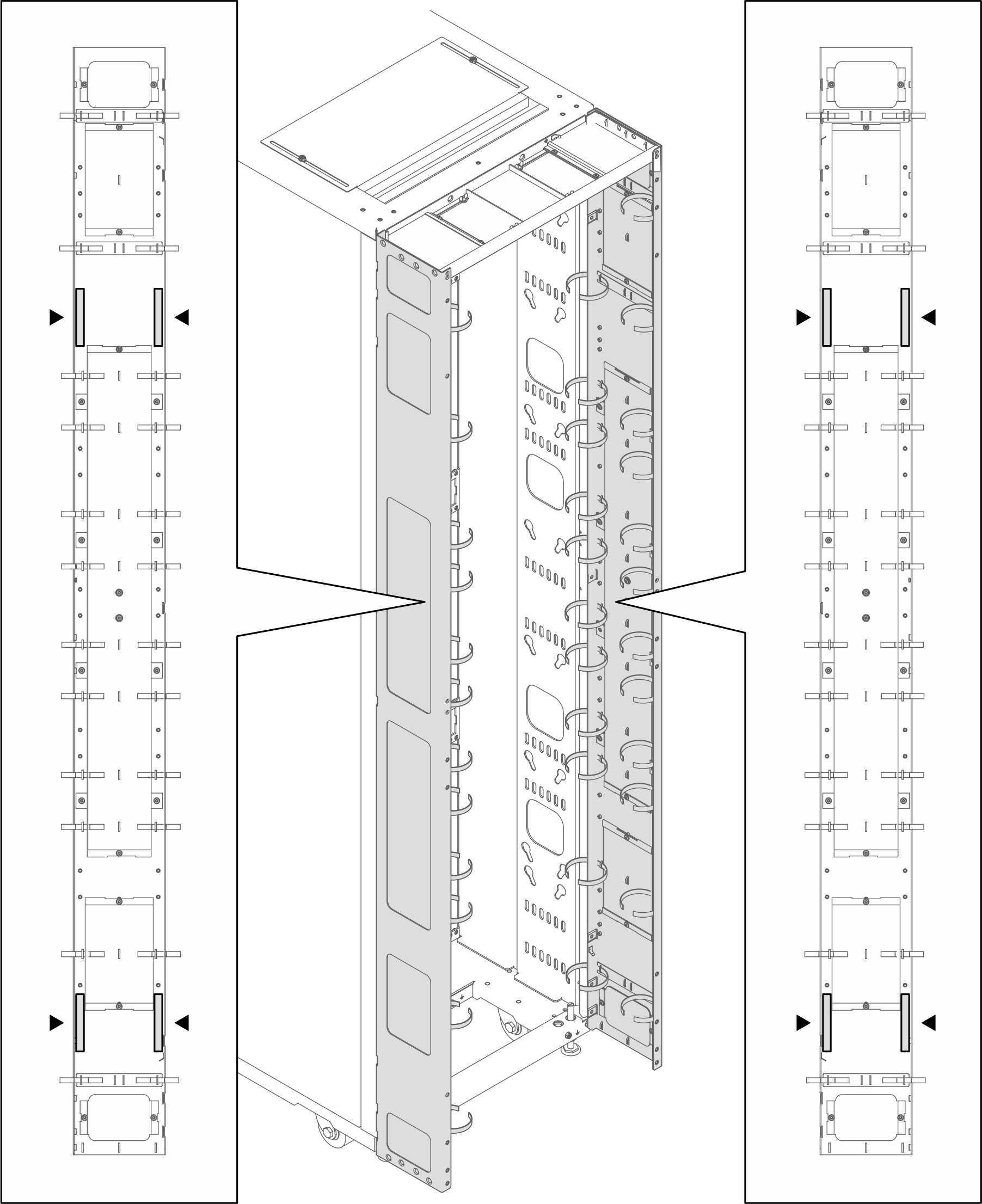
- 아래 그림은 브래킷 설치 위치를 보여줍니다.그림 10. 키홀 슬롯 2개가 있는 브래킷 설치 위치
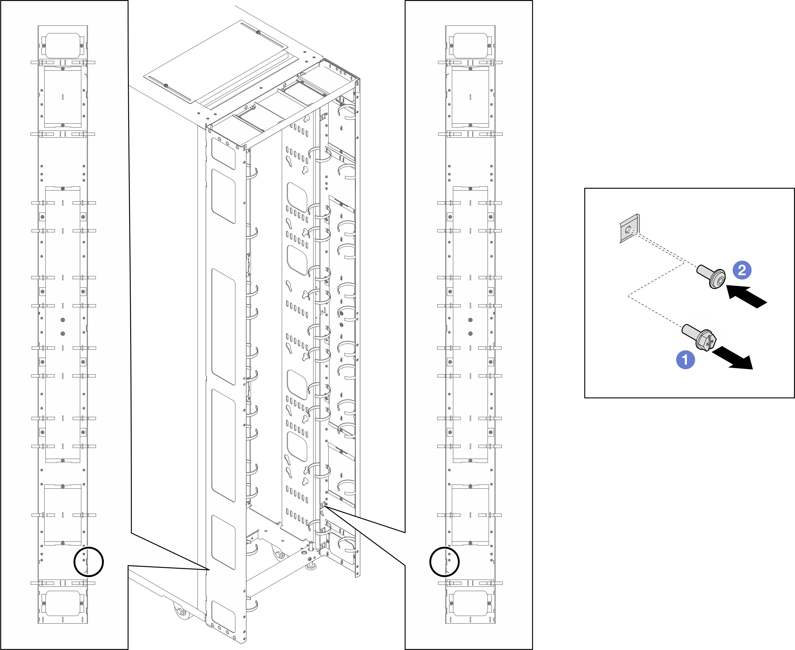
- 아래 그림에 표시된 위치에 브래킷 1개 또는 2개가 설치된 경우에는 M6 육각 머리 플랜지 나사를 M6 둥근 머리 플랜지 나사로 교체해야 합니다.그림 11. 나사 교체
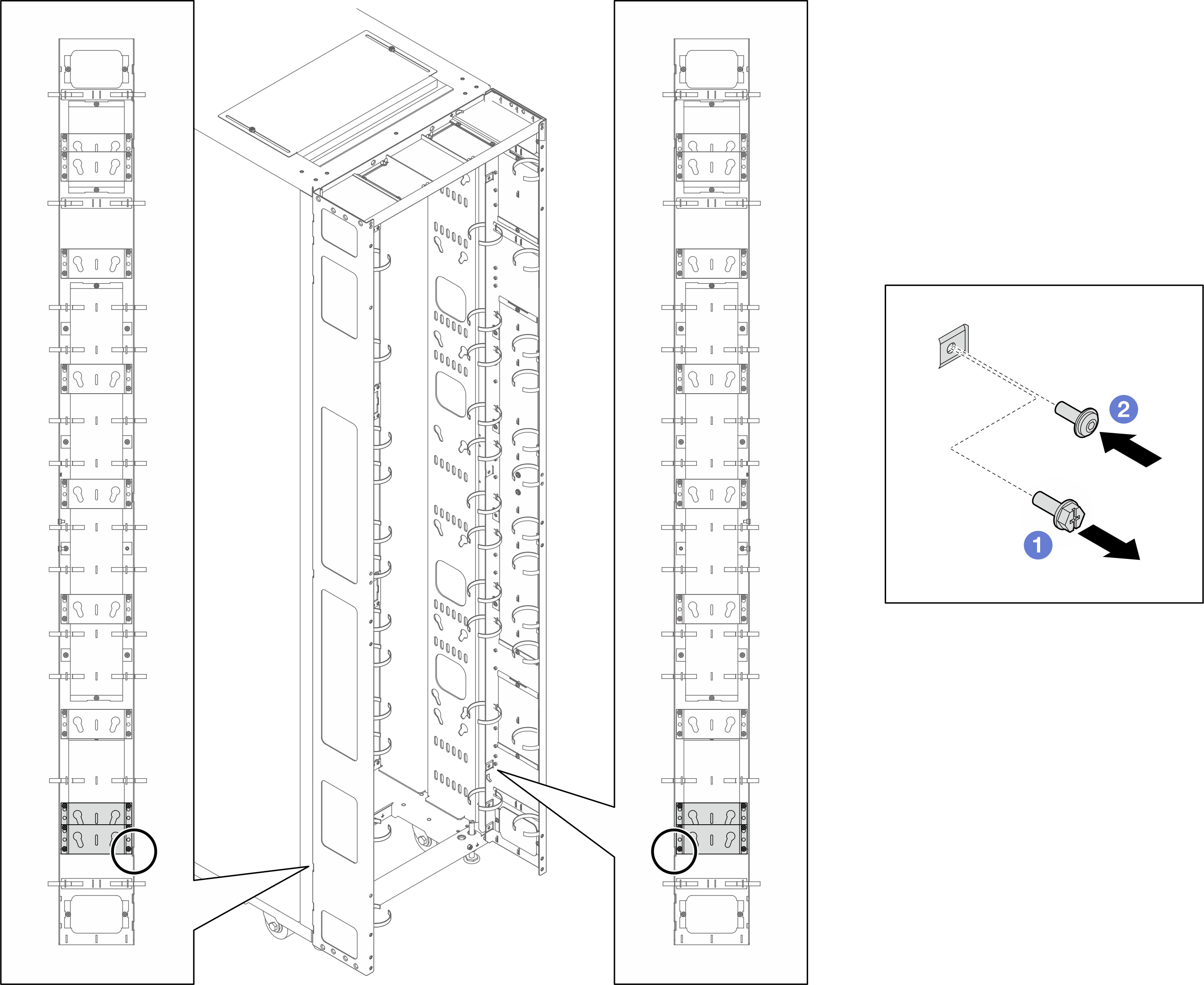
- M6 육각 머리 플랜지 나사를 제거합니다.
- M6 둥근 머리 플랜지 나사를 설치합니다.
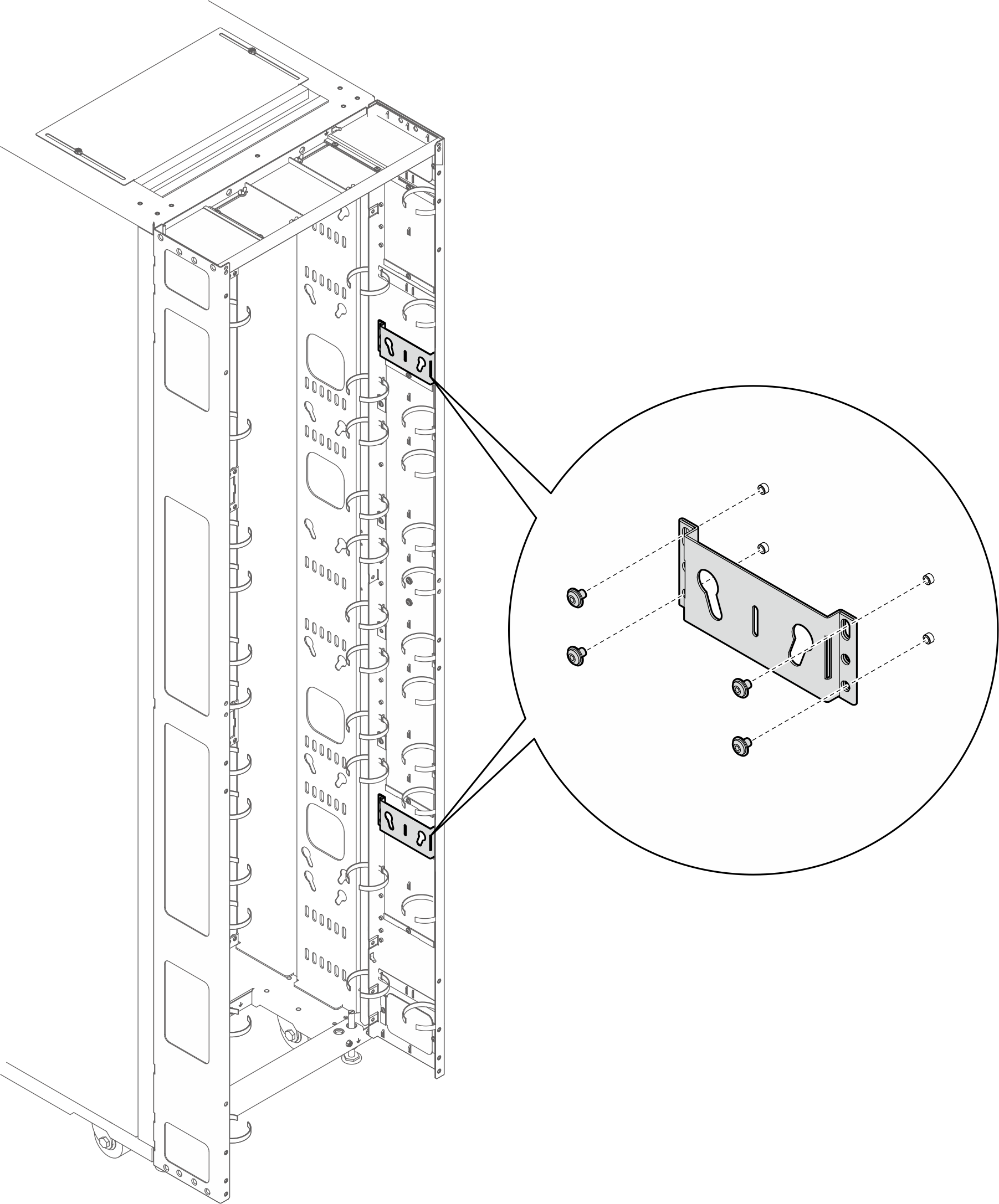
- 브래킷을 확장 패널에 맞추고 나사 4개로 고정합니다.그림 12. 키홀 슬롯 2개가 있는 브래킷 설치
- PDU 페그 2개를 브래킷의 키홀 슬롯에 삽입하고 PDU를 아래로 눌러 브래킷에 고정하십시오. 요구 사항에 따라 PDU를 설치할 왼쪽 또는 오른쪽 슬롯을 선택합니다.그림 13. PDU 설치
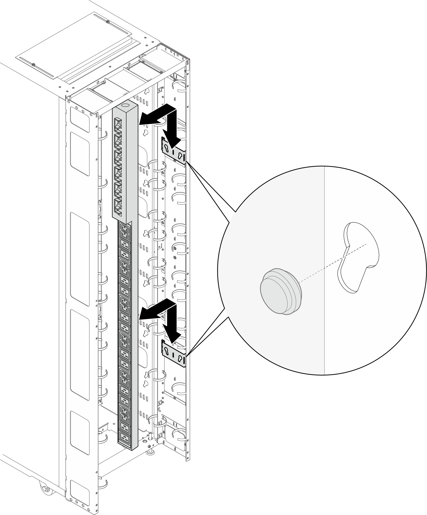 주PDU는 입력 케이블이 하단에 오도록 설치하기 위해 180도 회전 가능합니다.
- 아래 그림은 브래킷 설치 위치를 보여줍니다.
- L자형 브래킷(PDU 최대 2개, 또는 PDU 1개와 매니폴드 1개)주
- 아래 그림은 브래킷 설치 위치를 보여줍니다.그림 14. L자형 브래킷 설치 위치
- 아래 그림에 표시된 위치에 브래킷 1개 또는 2개가 설치된 경우에는 M6 육각 머리 플랜지 나사를 M6 둥근 머리 플랜지 나사로 교체해야 합니다.그림 15. 나사 교체
- M6 육각 머리 플랜지 나사를 제거합니다.
- M6 둥근 머리 플랜지 나사를 설치합니다.
- 브래킷을 확장 패널에 맞추고 나사 3개로 고정합니다. PDU의 방향에 따라 브래킷의 설치 위치를 선택하십시오.그림 16. PDU가 랙 캐비넷의 앞면을 향하도록 L자형 브래킷 설치
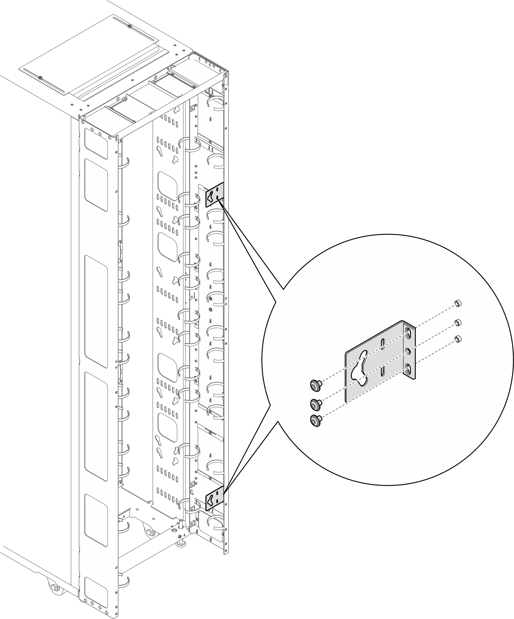 그림 17. PDU가 랙 캐비넷의 앞면을 향하도록 L자형 브래킷 설치
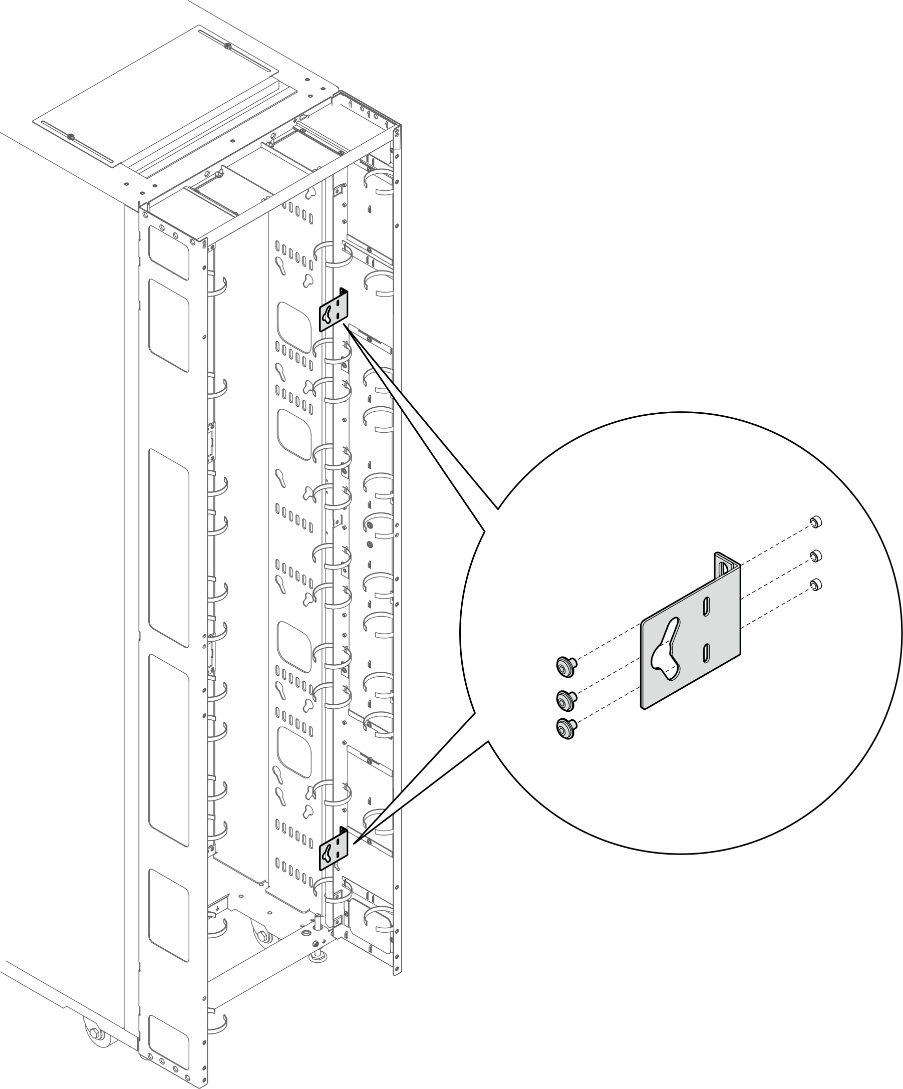
- PDU 페그 2개를 브래킷의 키홀 슬롯에 삽입하고 PDU를 아래로 눌러 브래킷에 고정하십시오.그림 18. PDU가 랙 캐비넷의 앞면을 향하도록 PDU 설치
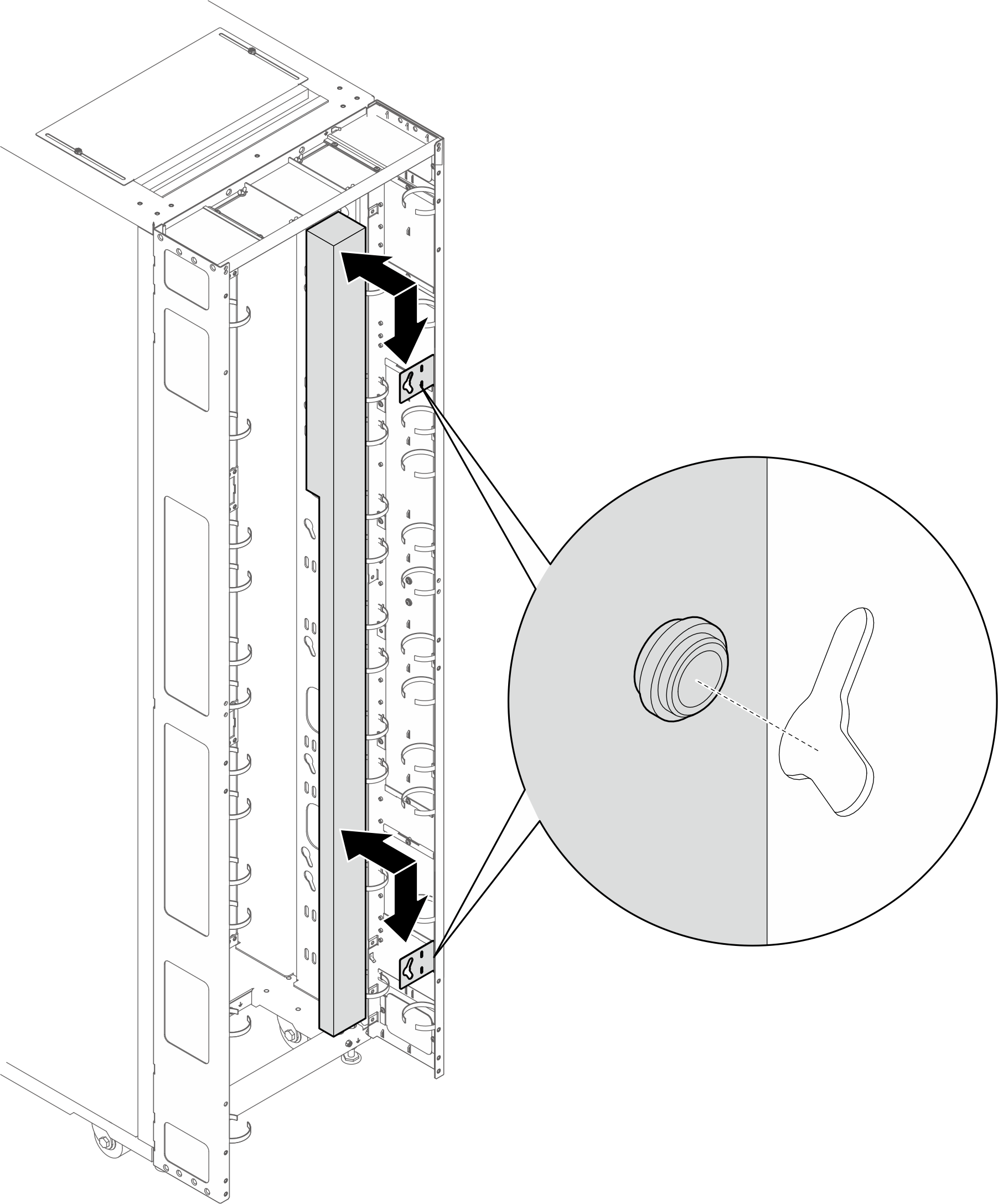 그림 19. PDU가 랙 캐비넷의 뒷면을 향하도록 PDU 설치
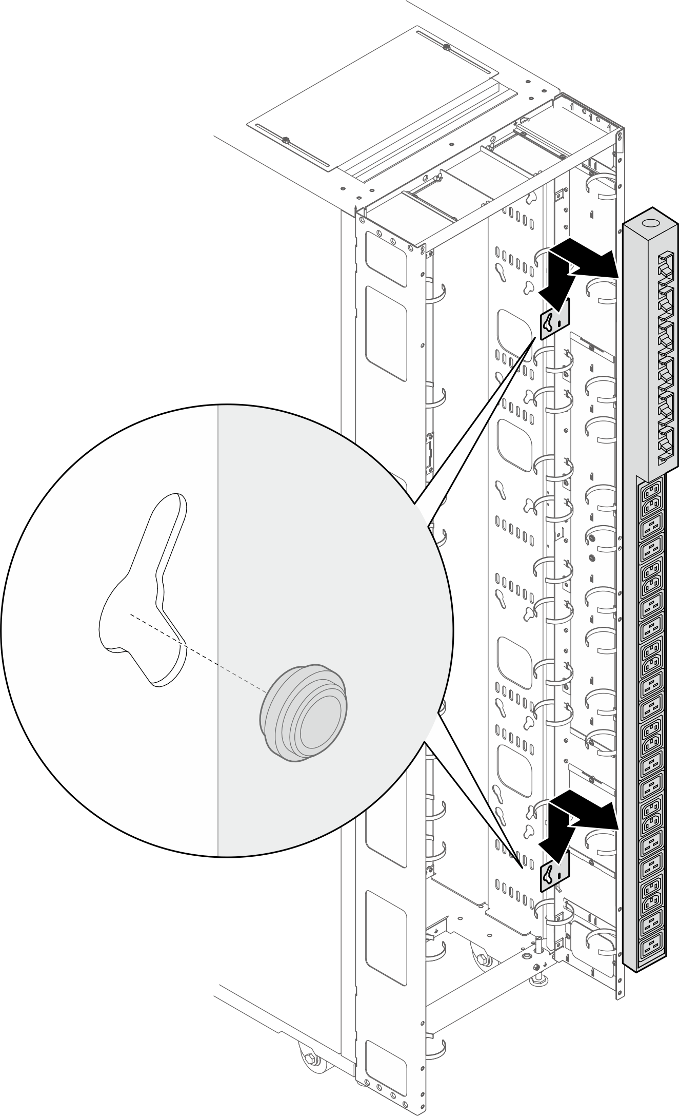
- 아래 그림은 브래킷 설치 위치를 보여줍니다.
- 요구 사항에 따라 다음 방법 중 하나를 선택하여 케이블을 배선할 충분한 공간을 확보하십시오.
브러시 패널 밀기
그림 20. 브러시 패널 밀기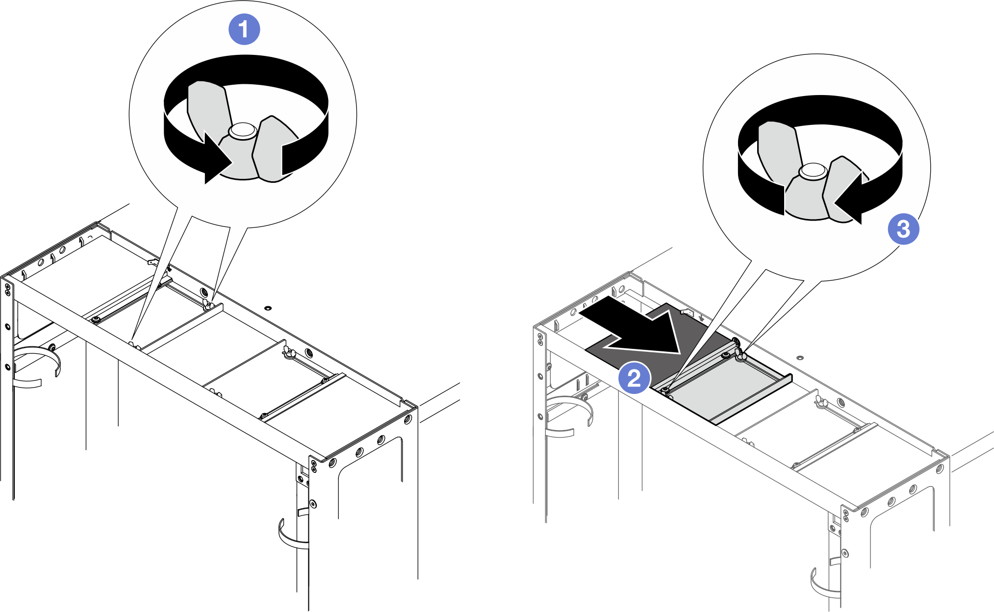
- 배플을 윗면 덮개에 고정하는 나사 2개를 풀어줍니다.
- 배플 및 브러시 패널을 윗면 덮개의 중앙을 향해 미십시오.
- 나사 2개를 조여 배플을 고정합니다.
브러쉬 패널 제거
그림 21. 브러시 패널 제거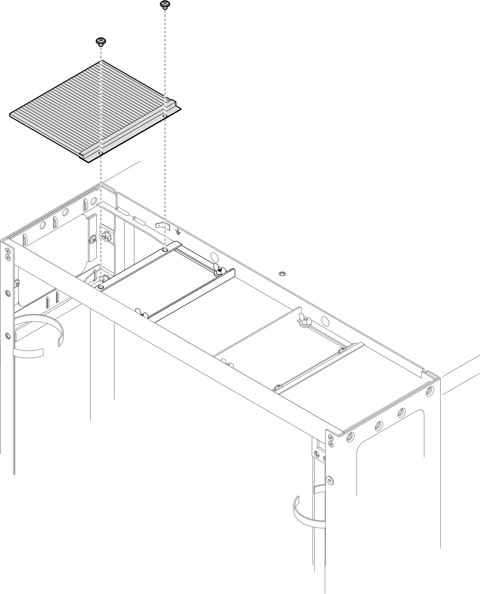
나사를 2개를 풀어 윗면 덮개에서 브러시 패널을 제거합니다.
브러시 패널 및 배플 제거
그림 22. 브러시 패널 및 배플 제거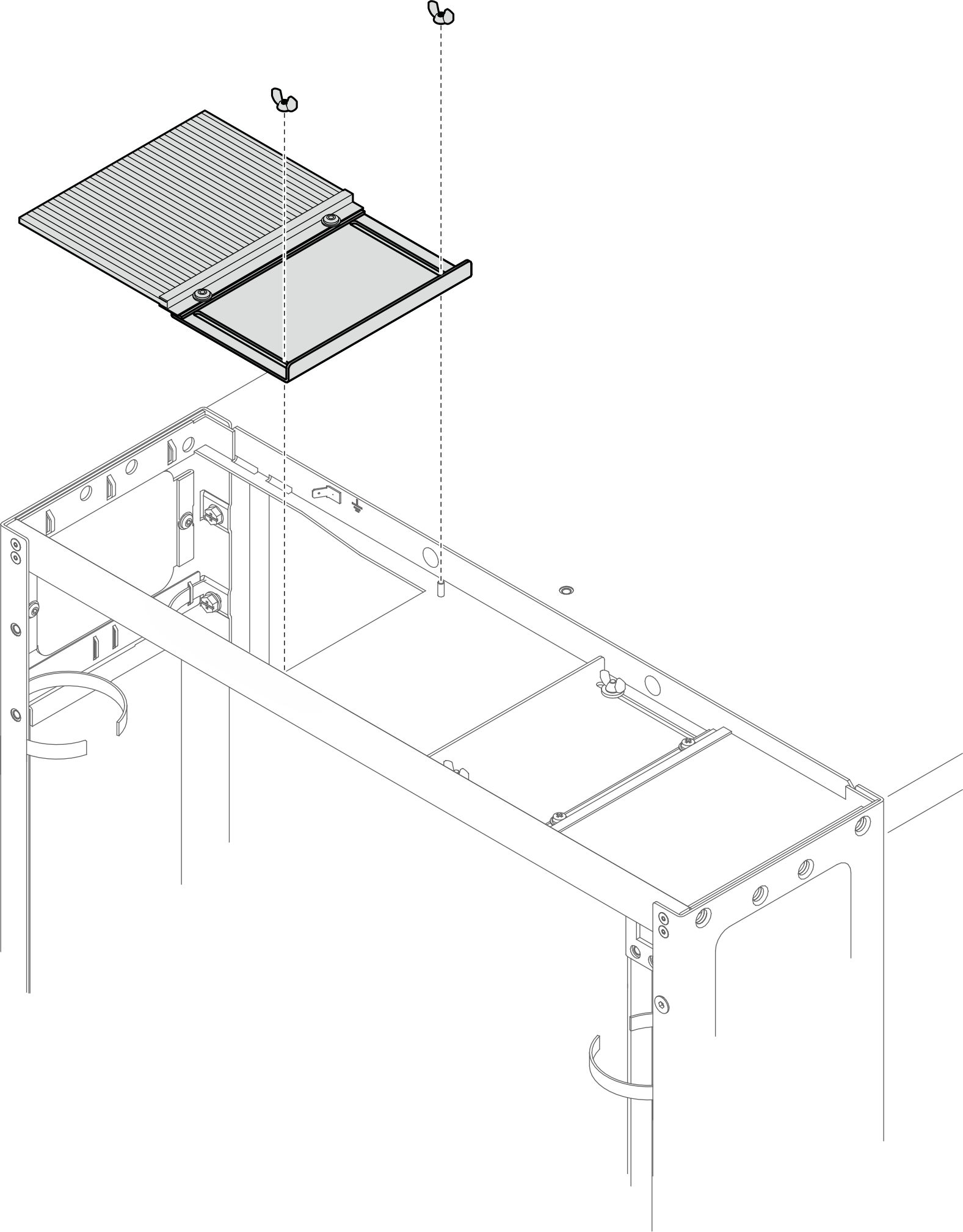
나사 2개를 풀어 윗면 덮개에서 브러시 패널 및 배플을 제거합니다.
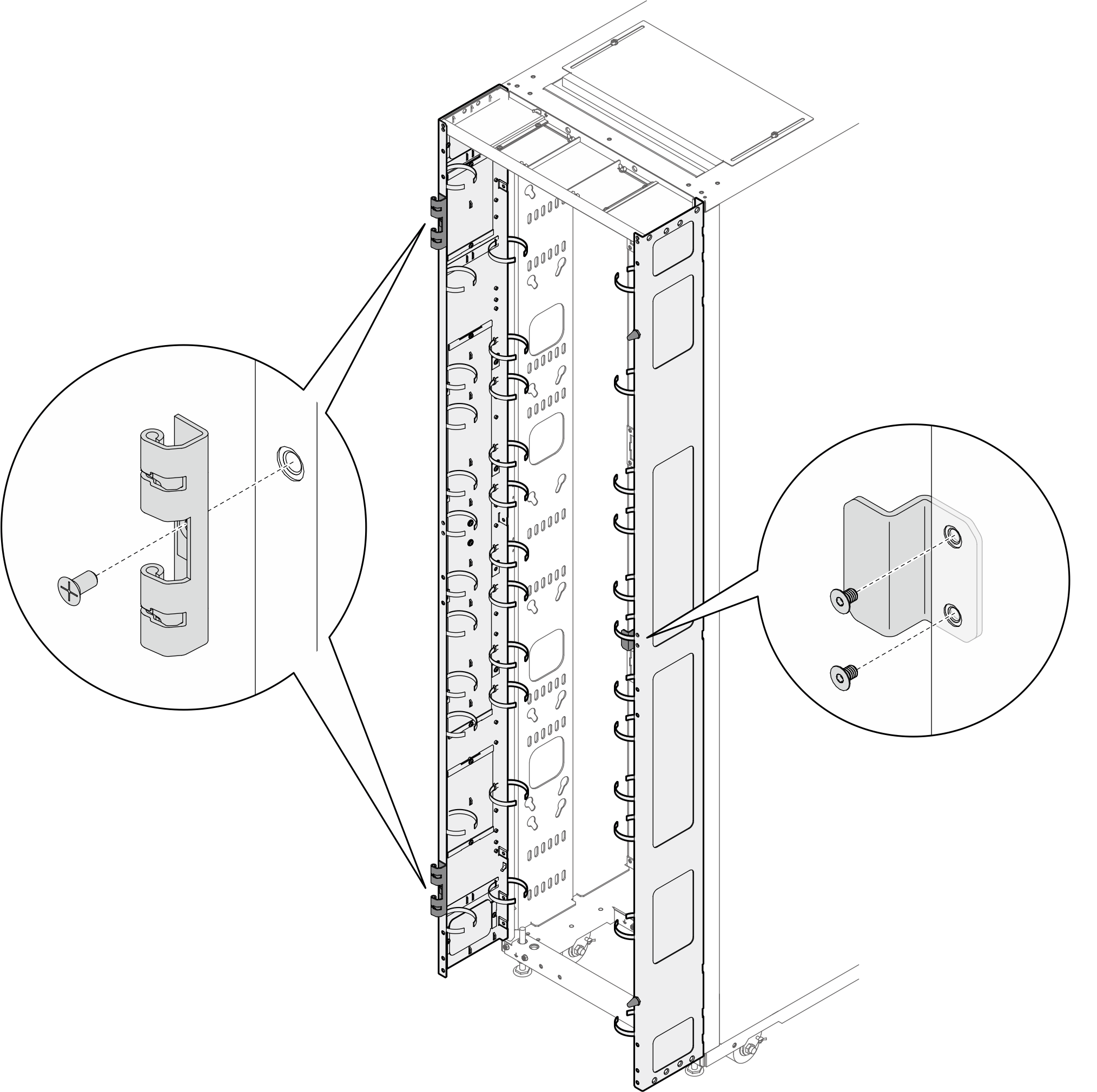
- 도어 힌지 2개 및 도어 래치를 확장 패널에 설치하십시오.그림 23. 도어 힌지 및 도어 래치 설치
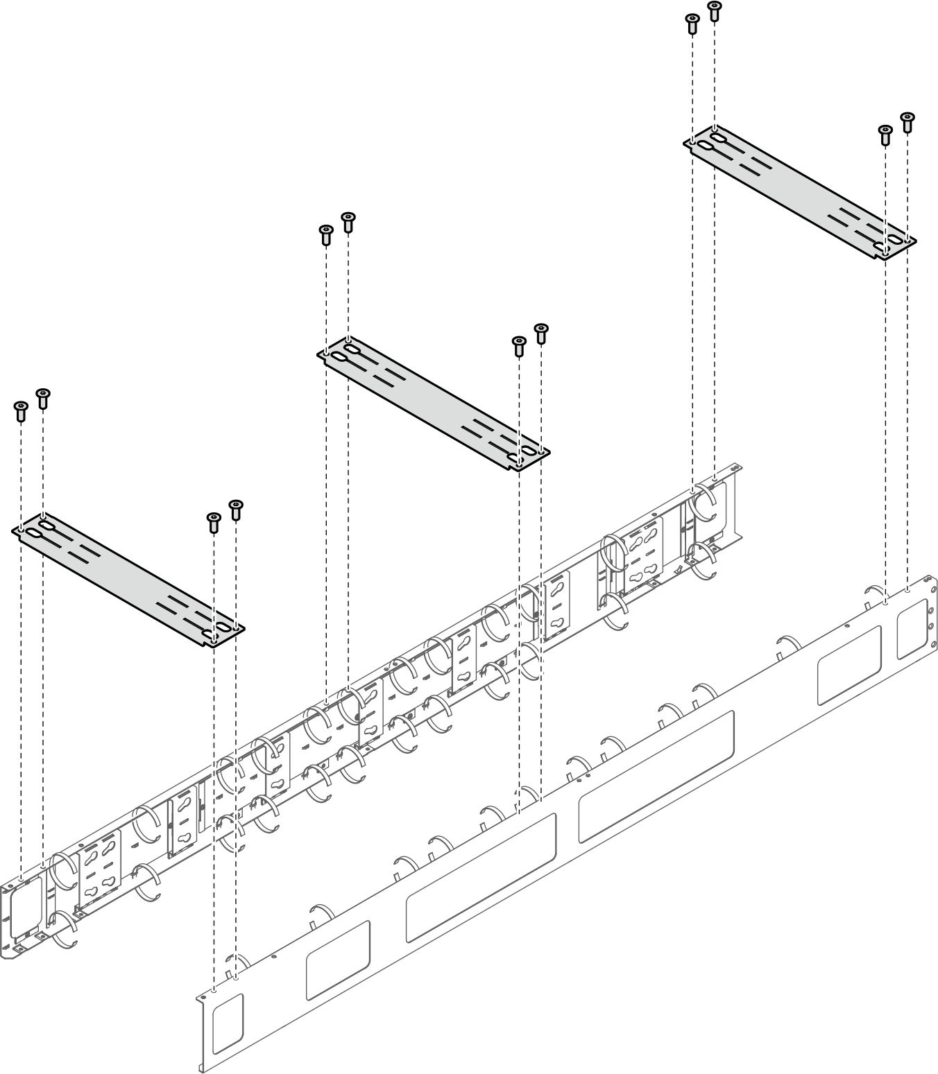
- 랙을 운송해야 하는 경우 지지 브래킷 3개를 설치하십시오.주요구 사항에 따라 현장 도착 시 지지 브래킷을 제거하십시오.그림 24. 지지 브래킷 설치
- 도어를 랙에 다시 설치합니다.그림 25. 도어 설치
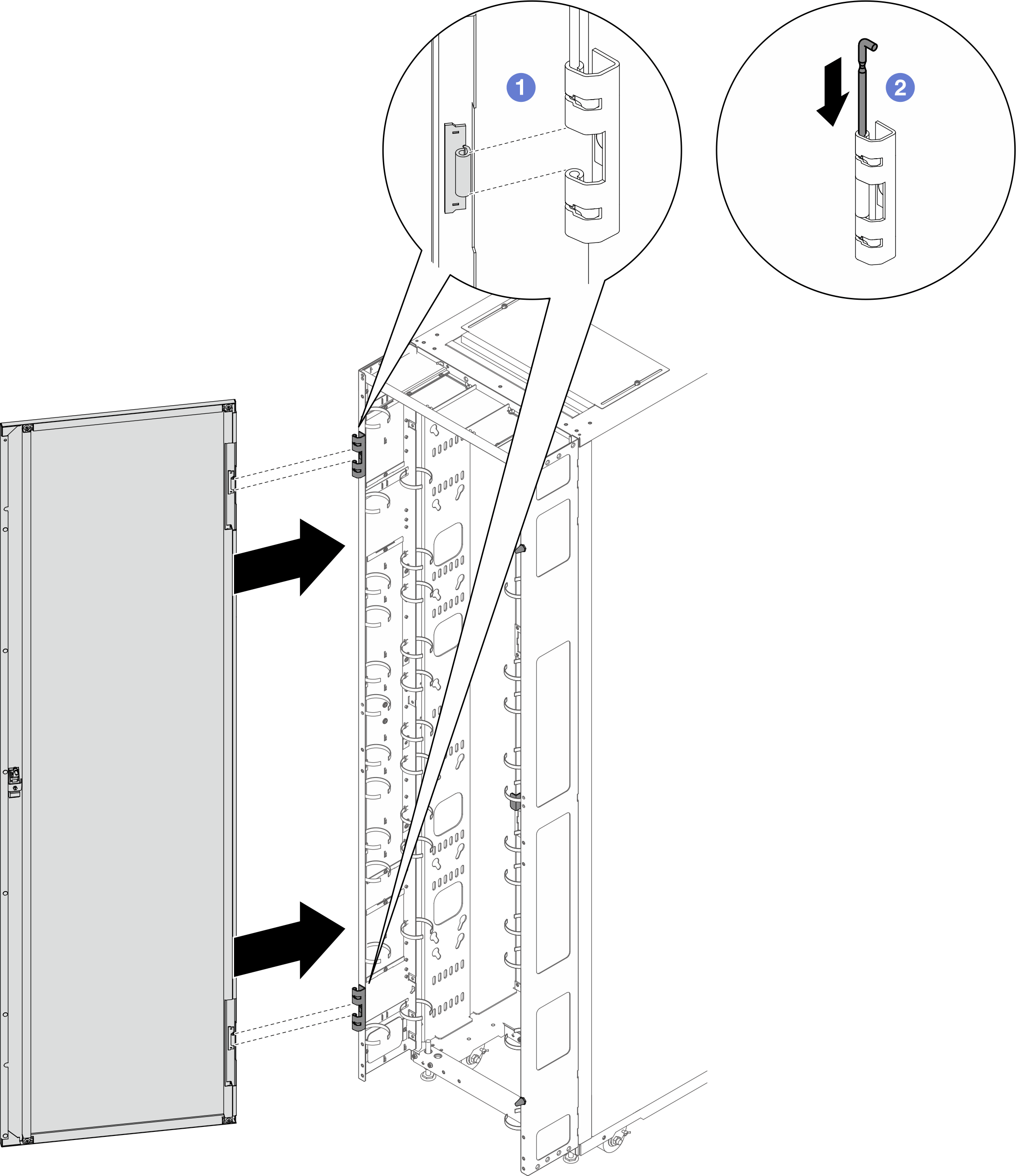
- 도어를 힌지에 맞추고 움직이지 않게 잡습니다.
- 도어가 고정되도록 힌지 핀을 닫힘 위치로 누릅니다.
피드백 보내기