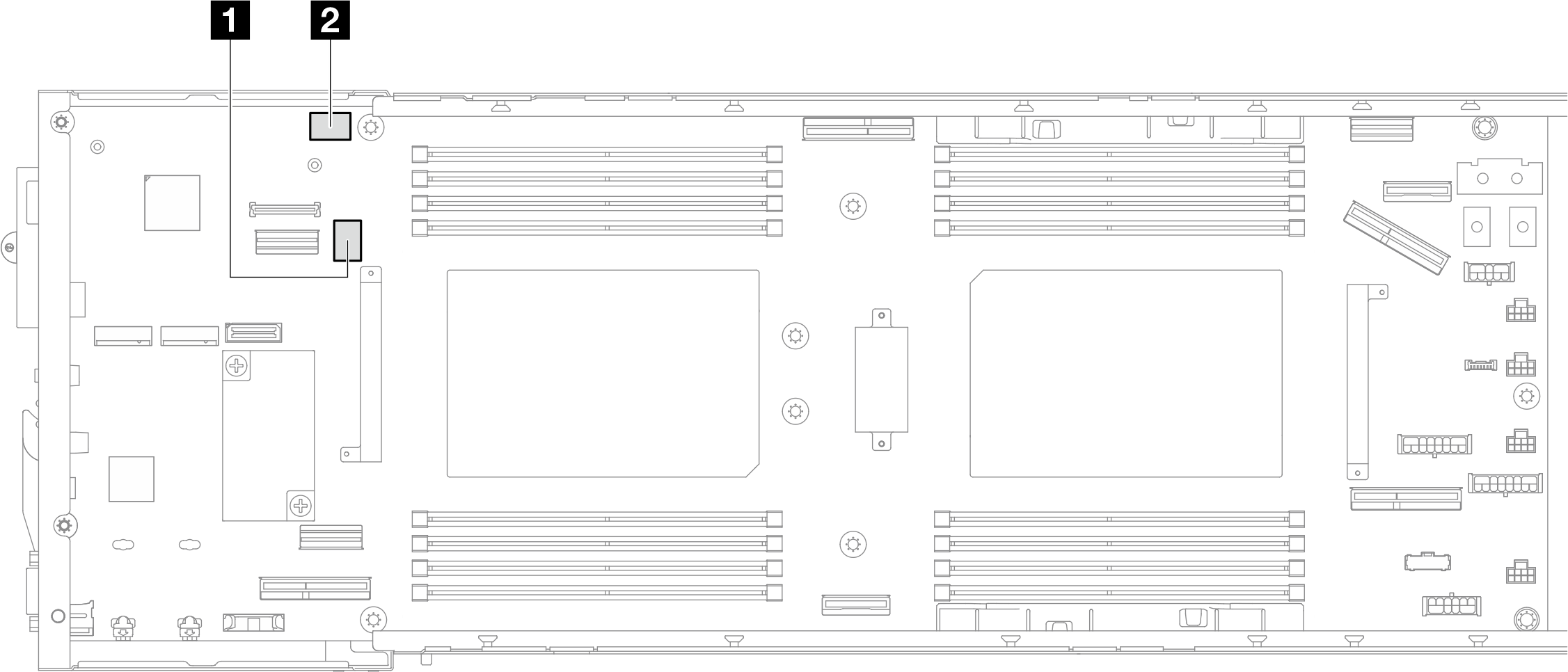
System-board switches
This section contains information on the location of the switches, jumpers, and buttons on the server.
Before you change any switch settings or move any jumpers, turn off the server; then, disconnect all power cords and external cables. Review the following information:
- Any system-board switch or jumper block that is not shown in the illustrations in this document are reserved.

| 1 SW5 | 2 SW13 |
SW5 switch block
| Switch number | Switch name | Usage description | |
|---|---|---|---|
| On | Off | ||
1 | Force BMC reset | Forces hot reset BMC chip | Normal (default) |
2 | Force BMC CPU reset | Forces warm XCC and CPU rest | Normal (default) |
3 | ME security override | Enables ME low security mode | Normal (default) |
4 | Password clear | Forces reset uEFI password | Normal (default) |
5 | Low security | Enables XCC low security mode | Normal (default) |
6 | ME recovery | Forces ME into recovery mode | Normal (default) |
7 | BMC force update | Forces XCC boot | Normal (default) |
8 | FPGA power permission override | Ignores Power Permission and allows system to power on | Normal (default) |
SW13 switch block
| Switch number | Switch name | Usage description | |
|---|---|---|---|
| On | Off | ||
1 | (Reserved) | (Reserved) | Normal (default) |
2 | Debug Atscale | Forces to enable the Atscale feature | Normal (default) |
3 | RTS (Real time clock) reset | Clears CMOS data | Normal (default) |
4 | FPGA MFG mode | Enables FPGA MFG mode | Normal (default) |
5 | Serial select | Normal (default) Sends uEFI debug message to serial port | Sends the XCC to serial port |
6 | (Reserved) | (Reserved) | Normal (default) |
7 | Bypass PFR | Enables bypass PFR | Normal (default) |
8 | BMC Trusted Platform Module (TPM) physical presence | Asserts TPM physical presence | Normal (default) |