2.5-inch drive backplane cable routing
Follow instructions in this section to route the cables for the 2.5-inch drive backplane.
Note
Connections between connectors; 1↔1, 2↔2, 3↔3, ... n↔n
When routing the cables, make sure that all cables are routed appropriately through the corresponding cable guides and cable clips.
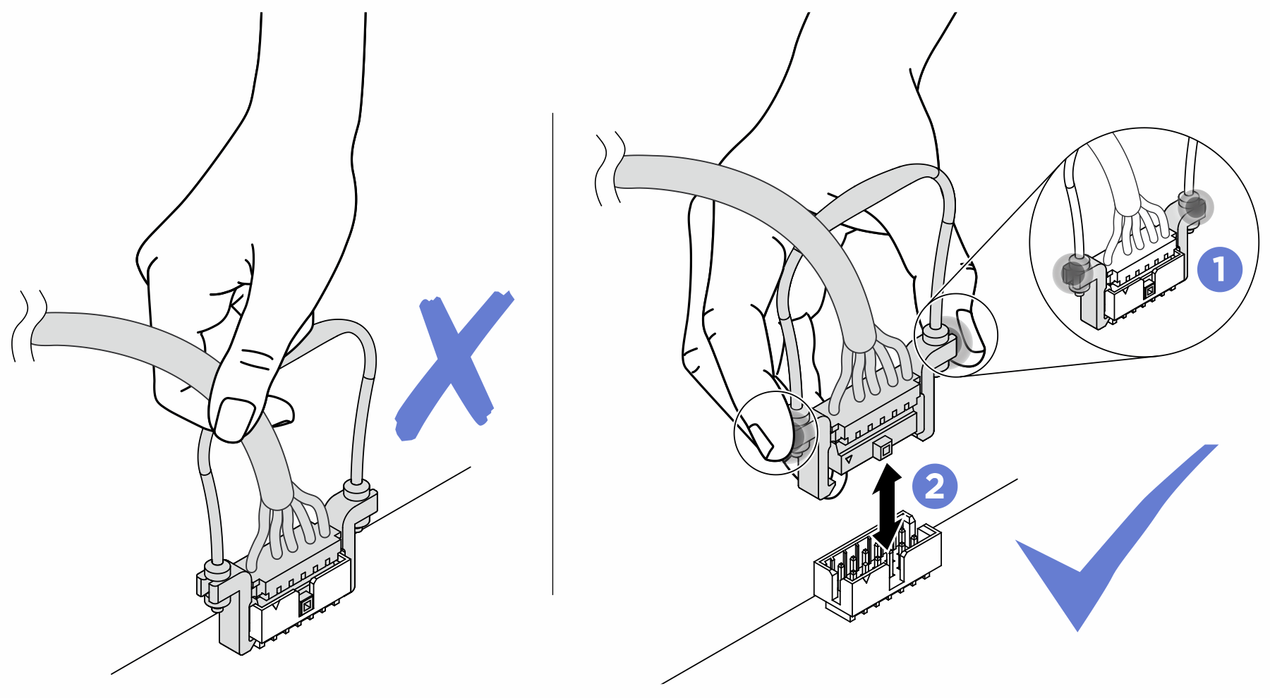
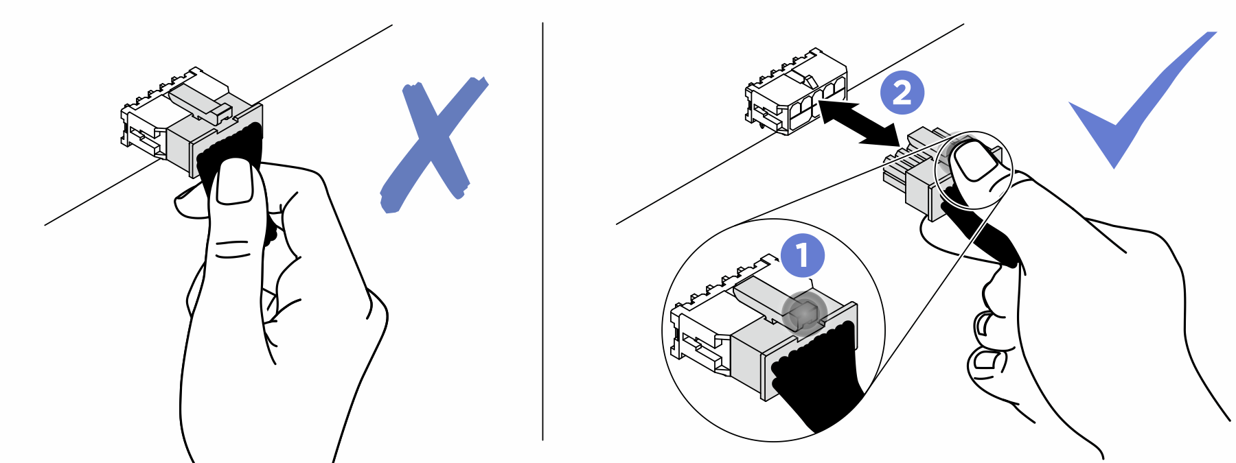
- Strictly observe the following instructions to avoid damaging cable sockets on the system board. Any damage to the cable sockets might require replacing the system board.
Connect cable connectors vertically or horizontally in alignment with the orientations of the corresponding cable sockets, avoiding any tilt.
- To disconnect cables from the system board, do as follows:
Press and hold all latches, release tabs, or locks on cable connectors to release the cable connectors.
- Remove the cable connectors vertically or horizontally in alignment with the orientations of the corresponding cable sockets, avoiding any tilt.NoteThe cable connectors might look different from those in the illustration, but the removal procedure is the same.

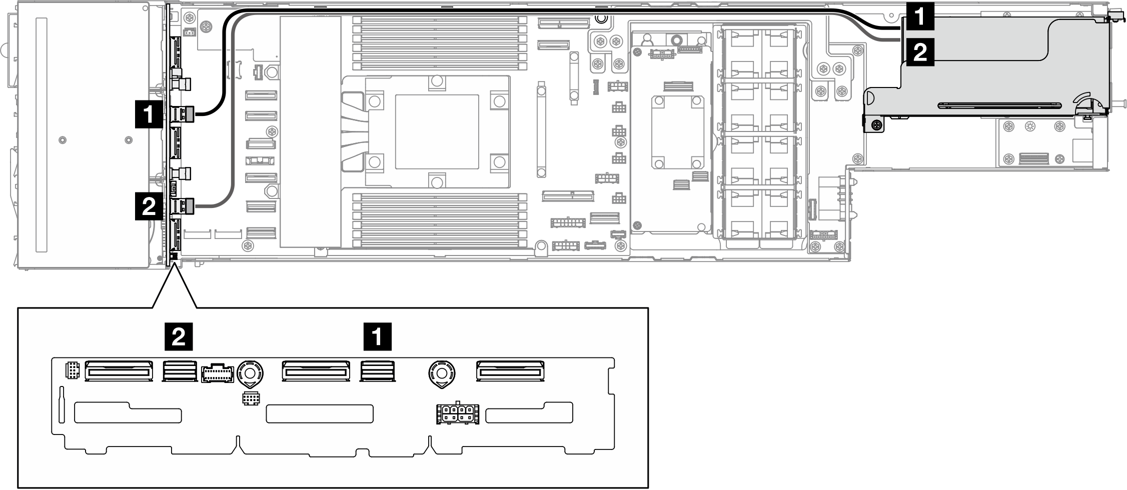
Drive backplane sideband and power cable routing
Figure 1. Drive backplane sideband and power cable routing
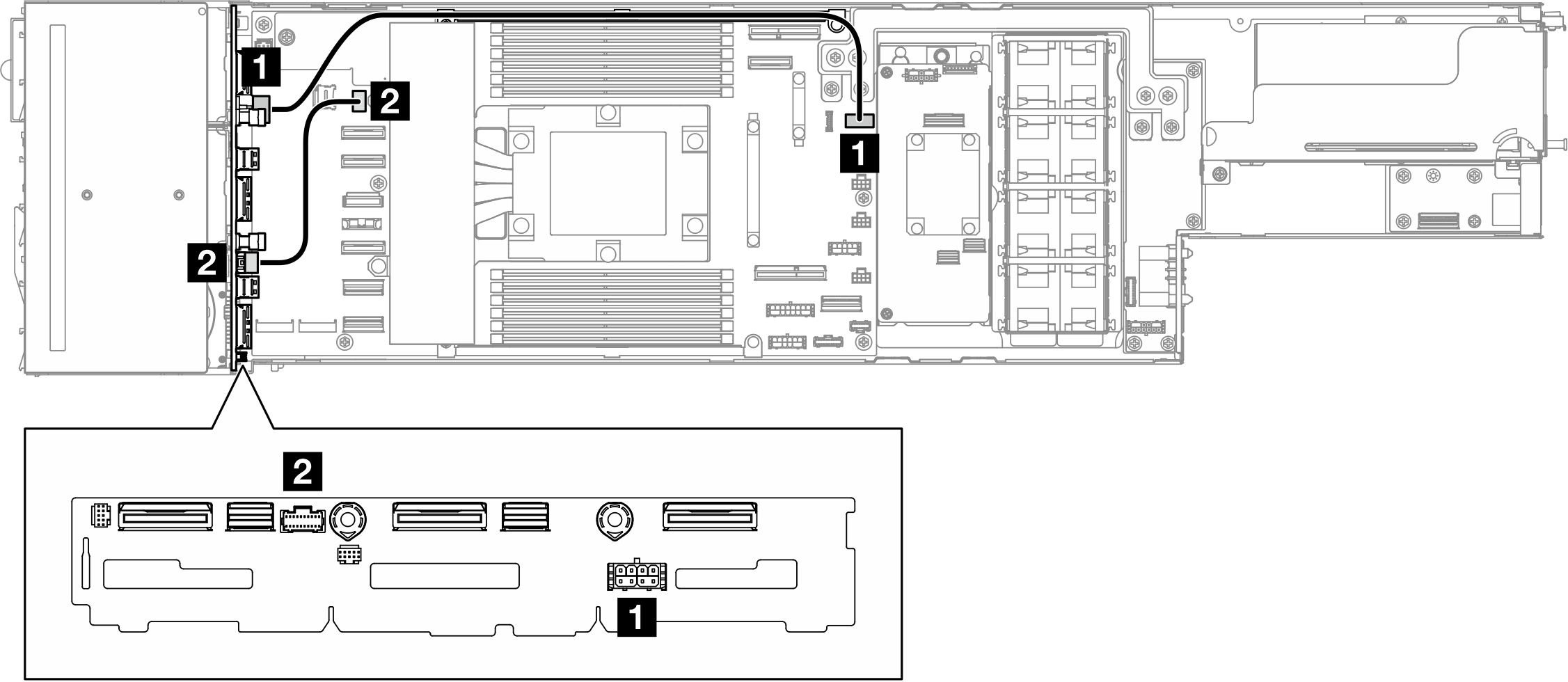
| From (2.5-inch drive backplane) | To (system board) | Cable |
|---|---|---|
| 1 Power connector | Drive backplane power connector | Power 2x4 pin to power 2x6 (4S/12P) pin (470 mm) |
| 2 Sideband connector | Drive backplane sideband connector | Sideband 2x10 to sideband 2x10 (150 mm) |
NVMe cable routing
Figure 2. NVMe cable routing
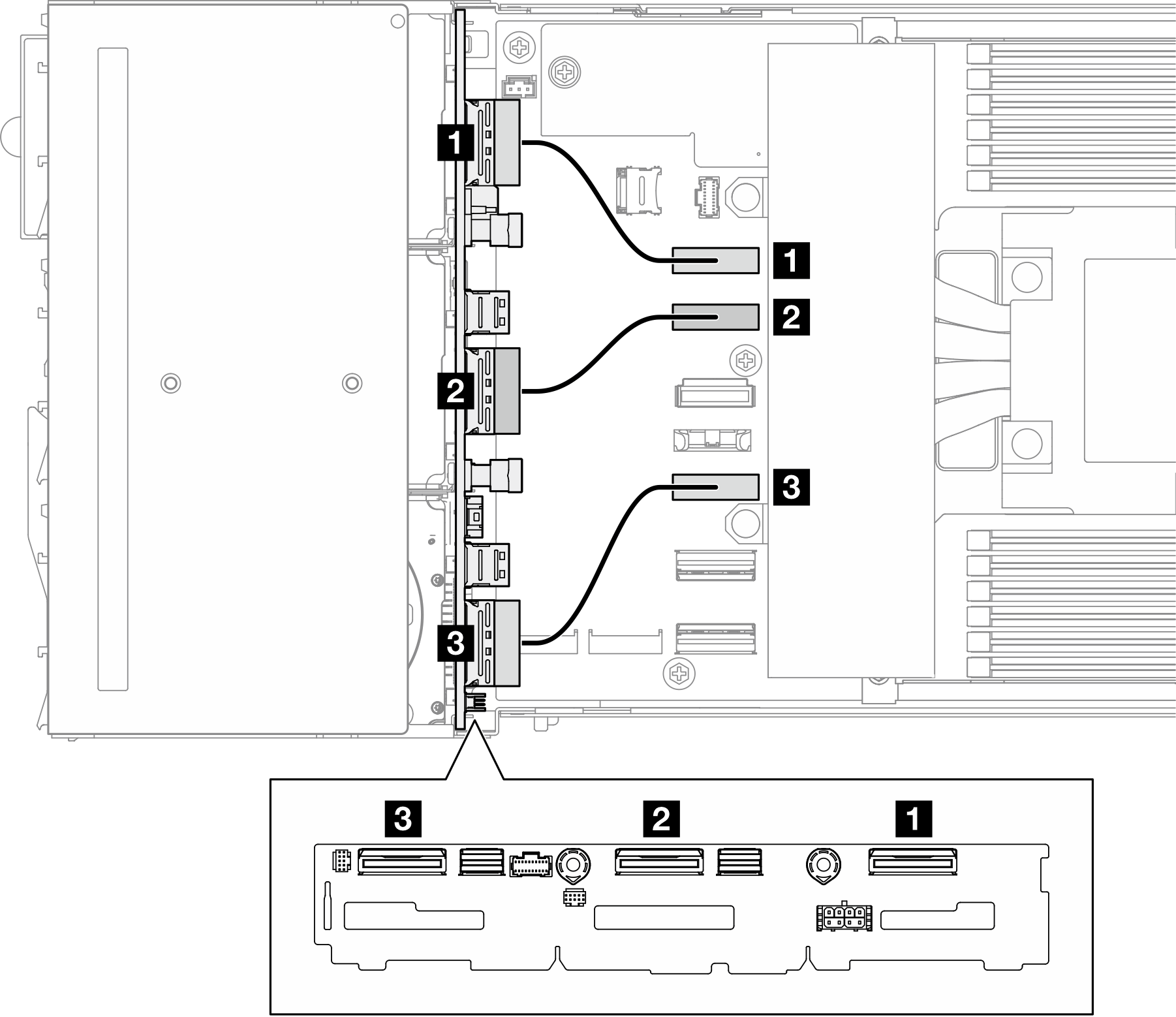
| From (2.5-inch drive backplane) | To (system board) | Cable |
|---|---|---|
| 1 NVMe 0-1 | NVMe 0-1 connector | MCIO x8 to MCIO x8 (100 mm) |
| 2 NVMe 2-3 | NVMe 2-3 connector | MCIO x8 to MCIO x8 (100 mm) |
| 3 NVMe 4-5 | NVMe 4-5 connector | MCIO x8 to MCIO x8 (100 mm) |
Onboard SATA cable routing
Figure 3. Onboard SATA cable routing
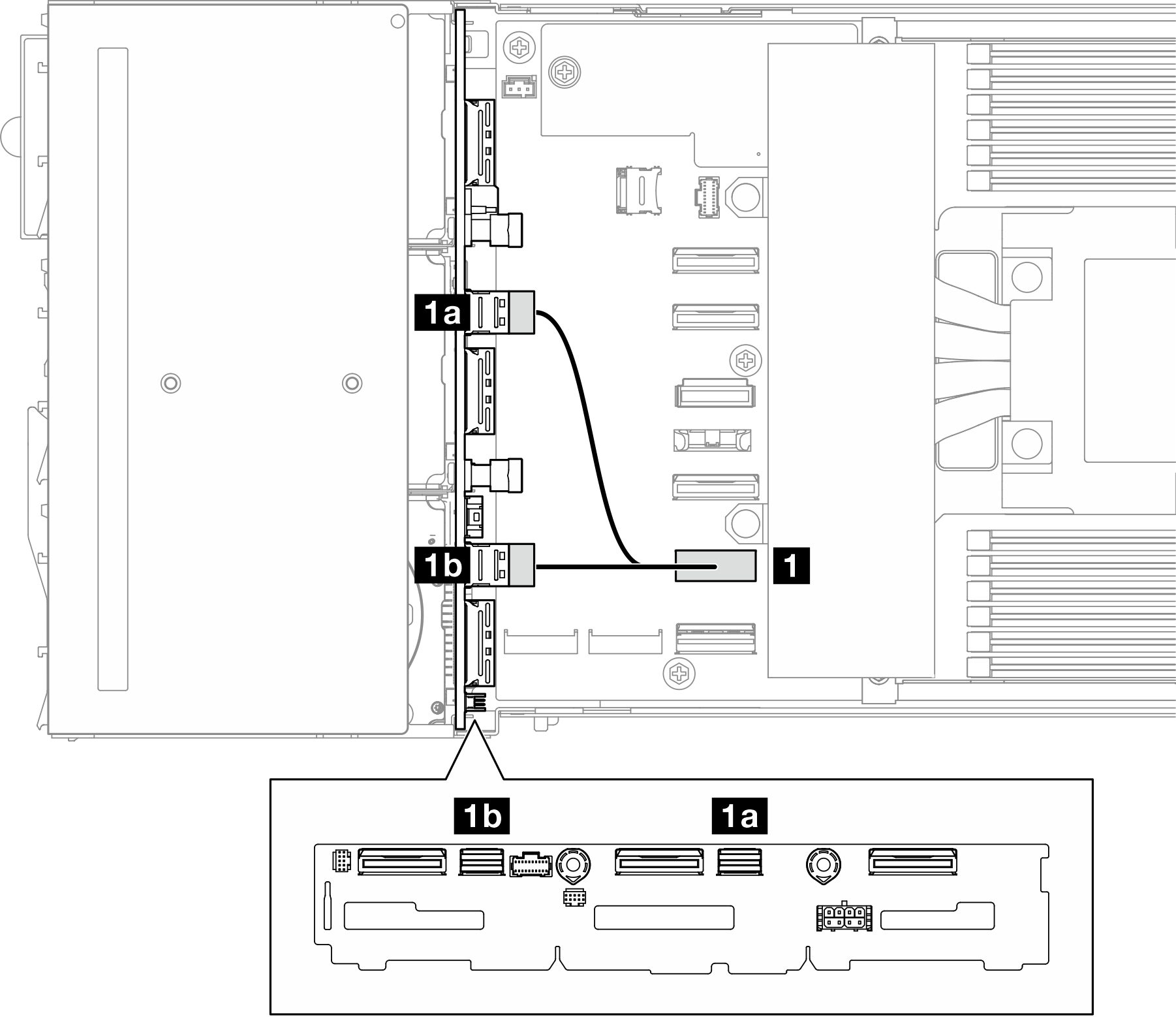
| From (2.5-inch drive backplane) | To (system board) | Cable |
|---|---|---|
| 1a SAS/SATA 0-3 | 1 SATA 0-5 connector | Low-profile SlimSAS x8 to 2 x SlimSAS x4 (115 mm / 65 mm) |
| 1b SAS/SATA 4-5 |
Internal CFF RAID SATA/SAS cable routing
Figure 4. CFF RAID cable routing
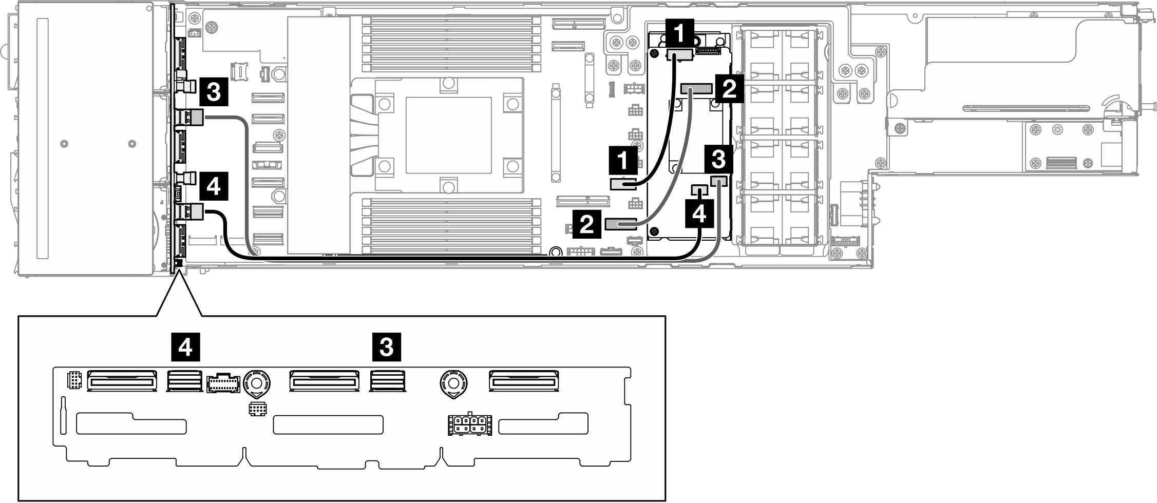
| From (system board, 2.5-inch drive backplane) | To (CFF RAID adapter) | Cable |
|---|---|---|
| 1 RAID power connector, system board | Power connector | Power 2x5 pin to power 2x5 pin (150 mm) |
| 2 RAID signal connector, system board | Signal connector | Low-profile SlimSAS x8 to SlimSAS x8 (150 mm) |
| 3 SAS/SATA 0-3 | SAS/SATA C0 connector | SlimSAS x4 to SlimSAS x4 (560 mm) |
| 4 SAS/SATA 4-5 | SAS/SATA C1 connector | SlimSAS x4 to SlimSAS x4 (460 mm) |
(Optional) If necessary, install the flash power module (see Install a flash power module); then, connect the flash power module cable and its extension cable to the CFF RAID adapter.
Figure 5. Flash power module extension cable
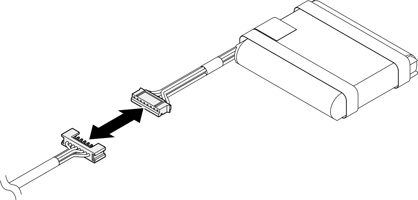
Figure 6. Flash power module cable routing
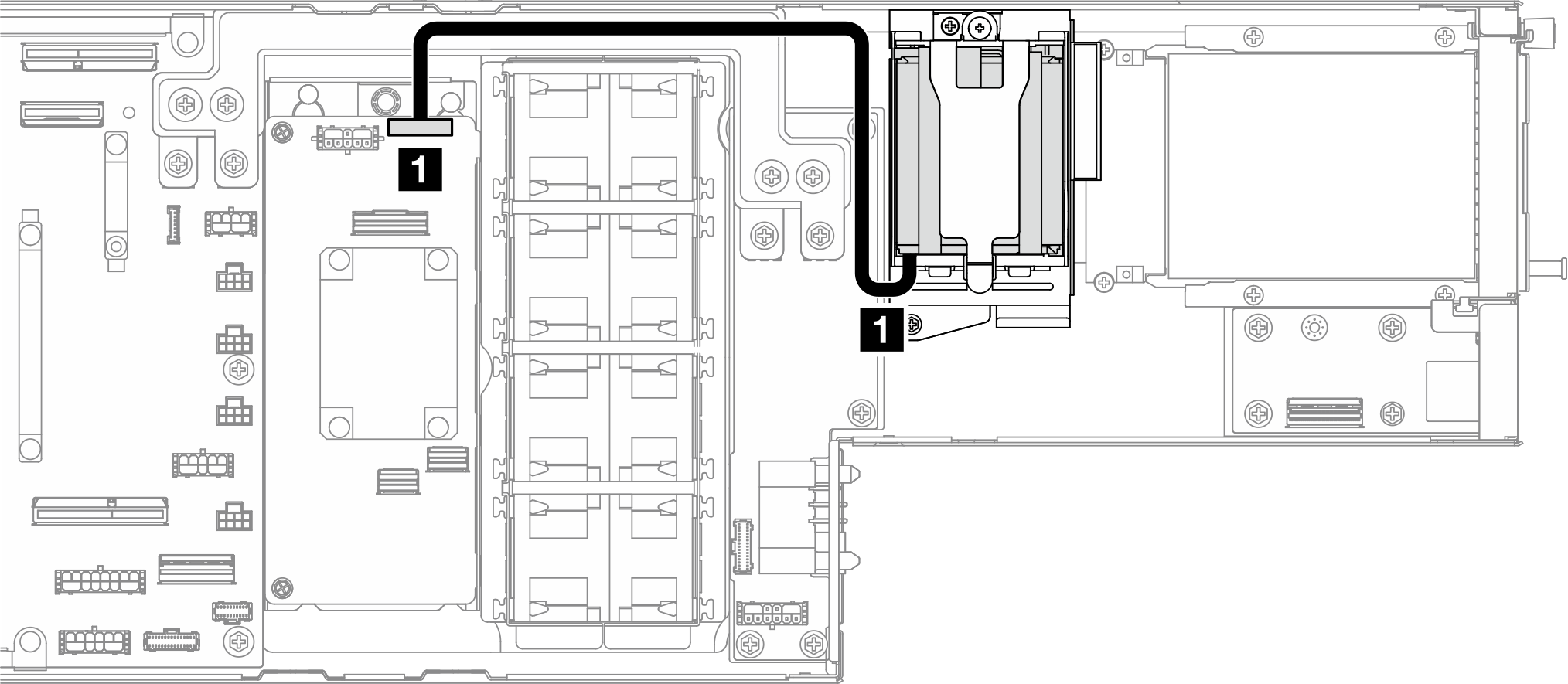
| From (Flash power module) | To (CFF RAID adapter) | Cable |
|---|---|---|
| 1 RAID flash power module connector | RAID flash power port on RAID adapter | Power 1x8 pin to power 1x8 pin |
8i RAID PCIe adapter SATA/SAS cable routing
Figure 7. 8i RAID PCIe adapter SATA/SAS cable routing
| From (2.5-inch drive backplane) | To (HBA/RAID adapter) | Cable |
|---|---|---|
| 1 SAS/SATA 0-3 | SAS/SATA C0 connector | SlimSAS x8 to 2 x SlimSAS x4 (650 mm / 730 mm) |
| 2 SAS/SATA 4-5 |
Give documentation feedback