Install a node to the chassis
Follow instructions in this section to install a node into the chassis.
About this task
To avoid potential danger, make sure to read and follow the safety information.

Read Installation Guidelines and Safety inspection checklist to make sure that you work safely.
Be careful when removing or installing the node to avoid damaging the node connectors.
When removing the node, note the node tray number and make sure to install the node in the same tray from which it was removed. Reinstalling the node into a different tray requires the node to be reconfigured.
The time required for a node to initialize varies by system configurations. The power LED flashes rapidly; the power button on the node will not respond until the power LED flashes slowly, indicating that the initialization process is complete.
- For proper cooling, each node tray must be installed with either a node or node tray fillers before the nodes in the chassis are powered on.
Depending on the specific configuration, the hardware might look slightly different from the illustrations in this section.
Procedure
- If necessary, remove the hose from the node filler.Figure 1. Hose removal from filler
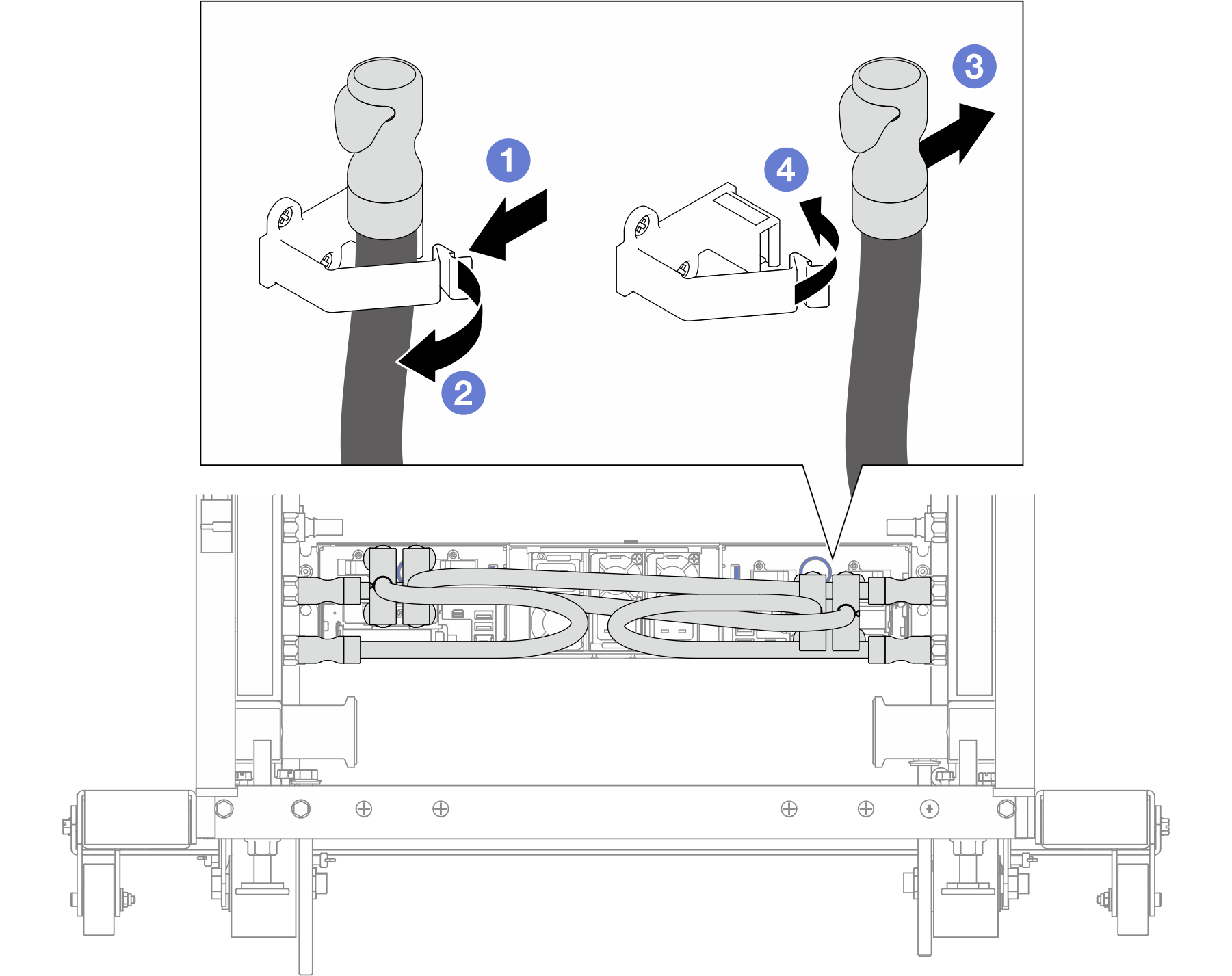
 Press the latch on the side of the clip.
 Open the clip.
 Remove the hose from the clip on node filler.
 Close the clip and secure it in place.
- If node tray fillers are installed, remove them from the chassis.
- Press and hold on the latch of the filler.
- Pull the filler out of the node tray.
Figure 2. Removal of a front node tray filler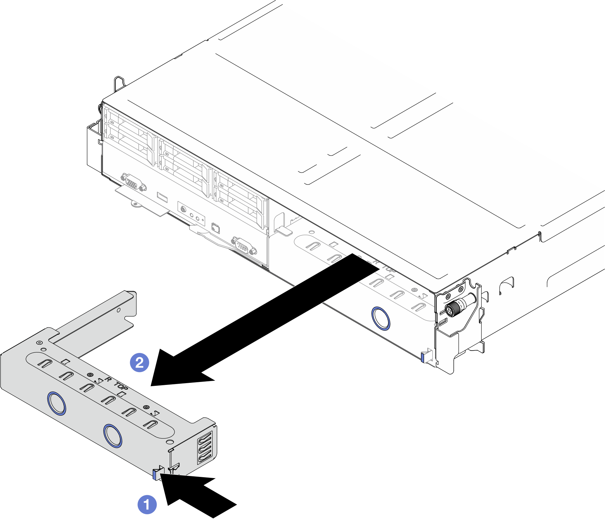 Figure 3. Removal of a rear node tray filler
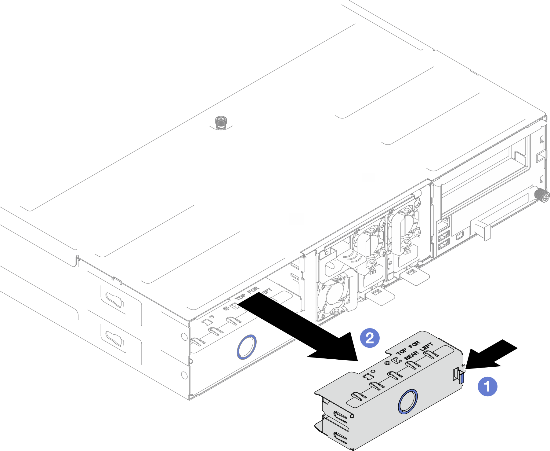
- Install the node into the chassis.
- Make sure that the front handle on the node is in the fully open position; then, slide the node into the node tray until it stops.
- Pivot the front handle to the fully closed position until the handle latch clicks.
Attention- For safety, make sure to hold the node with both hands when lifting the node.
- To avoid damage to the chassis midplane,
In the left tray (seen from the front), the node must be installed right-side up.
In the right tray (seen from the front), the node must be installed upside down.
Figure 4. Node installation to a left tray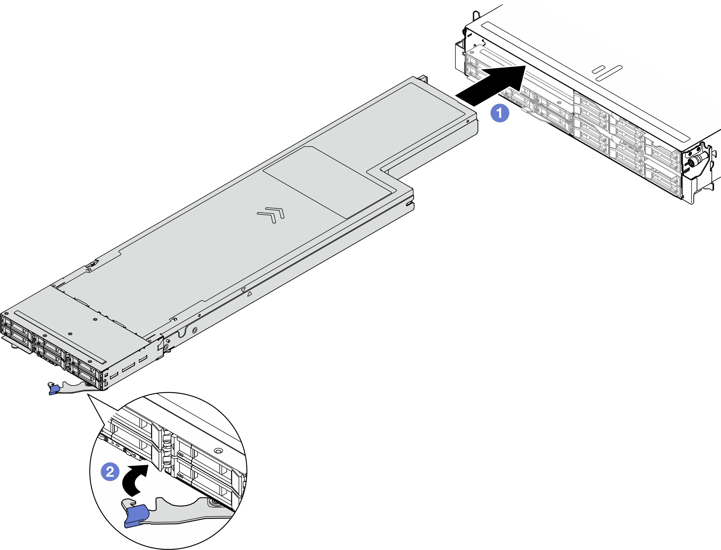 Figure 5. Node installation to a right tray
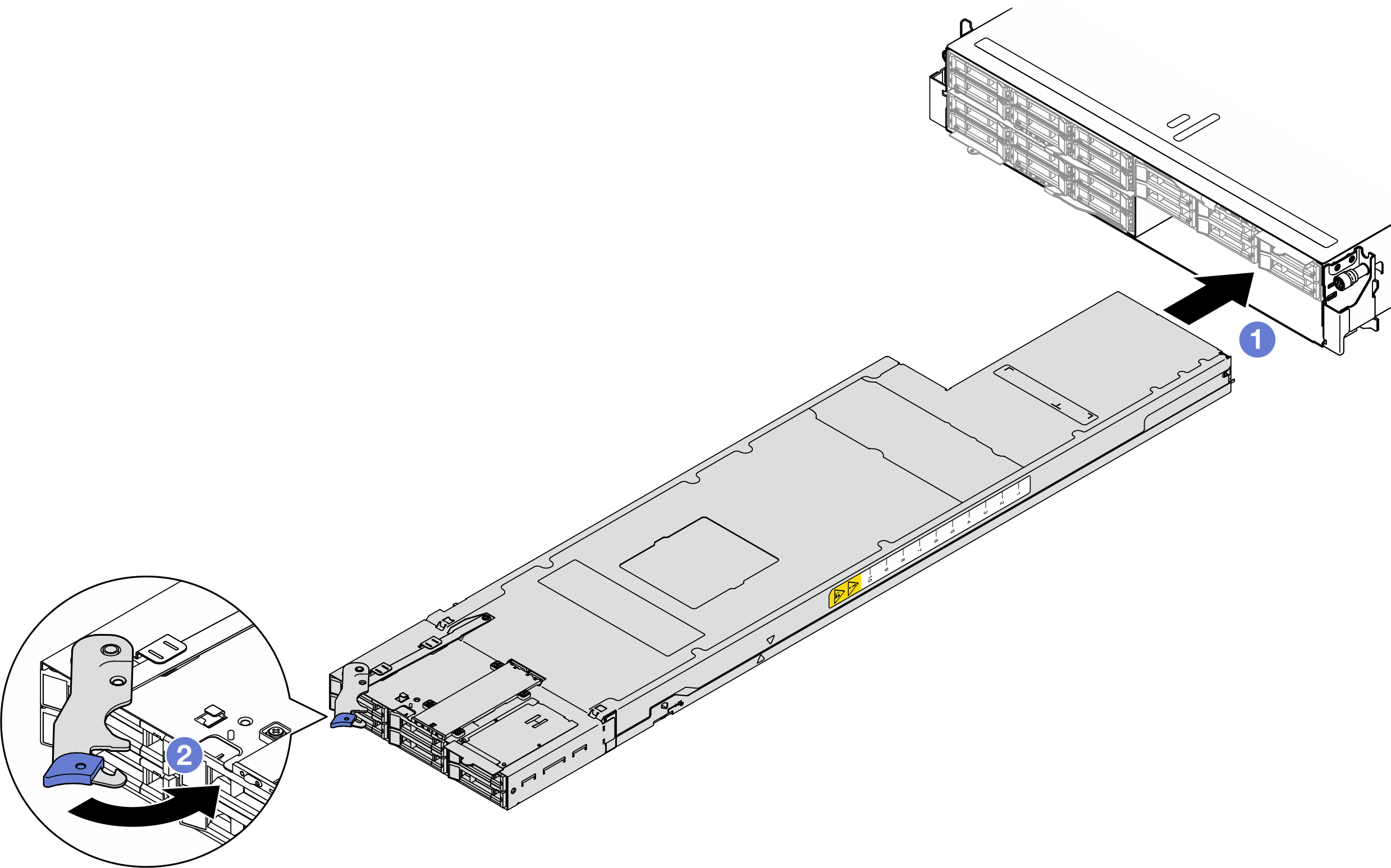
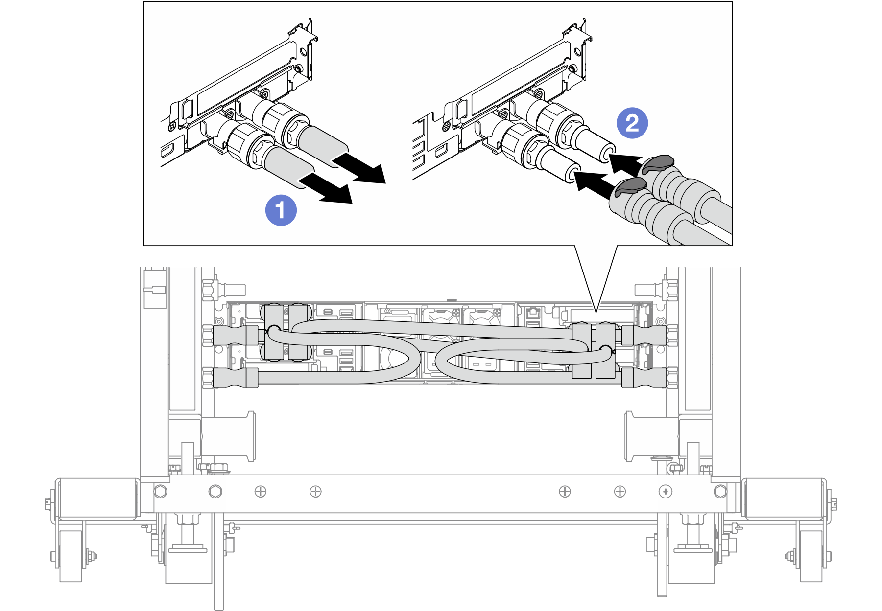
- For nodes with liquid-cooled configuration, connect the hoses to the rear of the node.
- Remove the quick connect plug covers on the rear of the node.
- Connect all the hoses to the node.Figure 6. Hose installation to node
- If necessary, install the hoses to the manifold.Figure 7. Installing the quick connect plug
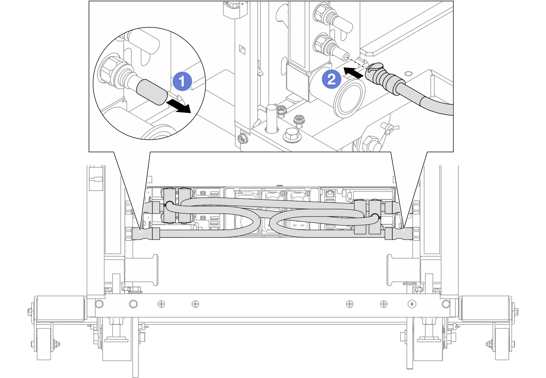
- Remove the rubber quick connect plug covers from the ports on the manifold.
- Connect the plug to the manifold port.
After you finish
- Install the quick connect plugs to the manifolds if the node needs to be connected to water. See Install the manifold (in-rack system) or Install the manifold (in-row system).
- Make sure that the required power supply units are installed and power cords are connected; then, power on the node (see Install a hot-swap power supply and Power on the node).
- Check the power LED to make sure it transitions between fast blink and slow blink to indicate the node is ready to be powered on; then, power on the node.
- Make sure that the power LED is lit continuously, indicating that the node is receiving power and is turned on.
- If this is the initial installation of the node into the chassis, you must configure the node through the Lenovo XClarity Provisioning Manager and install the node operating system (see Lenovo XClarity Provisioning Manager portal page).
- If the node access over local console is not available, refer to the following sections in the XCC documentation compatible with your node at Lenovo XClarity Controller portal page.
- Access Lenovo XClarity Controller web interface (see “Accessing the XClarity Controller web interface” section).
- Set up Lenovo XClarity Controller network connection through Lenovo XClarity Provisioning Manager (see “Setting up the XClarity Controller network connection through the XClarity Provisioning Manager” section).
- Log in to Lenovo XClarity Controller (see “Logging in to the XClarity Controller” section).
- If you have changed the configuration of the node, or if you are installing a different node from the one that you removed, make sure to configure the node through the Setup utility, and you might have to install the node operating system. For more details, see System configuration.
- You can place the identifying information on the pull-out label tab that are accessible on the front of the node (see Identify the system and access the Lenovo XClarity Controller).
Demo video