Memory module installation rules and order
Memory modules must be installed in a specific order based on the memory configuration that you implement and the number of processors and memory modules installed in the server.
Supported memory types
For information on the types of memory module supported by this server, see Memory section in Technical Specifications.
Information about optimizing memory performance and configuring memory is available at the Lenovo Press website:
In addition, you can take advantage of a memory configurator, which is available at the following site:
Lenovo Enterprise Solutions Configurator (Memory Configurations)
For the specific information about the required installation order of memory modules in SD535 V3 based on the system configuration and memory mode that you are implementing, see below.
Memory modules and processor layout
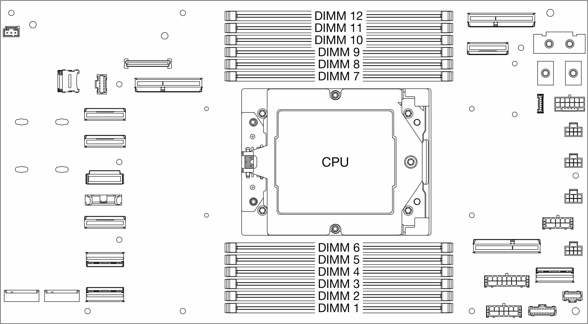
The memory-channel configuration table below shows the relationship between the processors, memory controllers, memory channels, and memory module slot numbers.
| UMC No. | 8 | 7 | 11 | 6 | 10 | 9 | 3 | 4 | 0 | 5 | 1 | 2 |
| Channel No. | L | K | J | I | H | G | A | B | C | D | E | F |
| DIMM No. | 12 | 11 | 10 | 9 | 8 | 7 | 6 | 5 | 4 | 3 | 2 | 1 |
Memory module installation guideline
Follow the rules below when installing DIMMs:
Mixing DIMMs from different vendors is supported in a system.
Mixing x4 and x8 DIMMs is not allowed in a system.
Mixing 3DS RDIMM and non-3DS RDIMM is not allowed in a system.
Mixing 4-rank 3DS RDIMM and 8-rank 3DS RDIMM is not allowed in a system.
Mixing 16Gbit (16GB, 32GB, 64GB), 24Gbit (24GB, 48GB, 96GB) and 32Gbit (128GB) memory module is not allowed in a system with Genoa processor.
Mixing 16Gbit (16GB, 32GB, 64GB), 24Gbit (24GB, 48GB, 96GB) and 32Gbit (128GB) memory module is allowed in a system with Turin processor.
Single-rank and dual-rank DIMM mixing is allowed in a system.
When installing DIMMs with different capacity, install the DIMM with the highest capacity first following population sequence.
For best performance, the population recommends identical memory capacity and rank across all 12 channels.
Memory module installation order
S1-S12 indicate DIMM slots 1-12.
1-12 indicate the installation order.
The following table shows the DIMM population sequence.
| Total DIMMs | Slot number | ||||||||||||
| S12 | S11 | S10 | S9 | S8 | S7 | S6 | S5 | S4 | S3 | S2 | S1 | ||
| 1 DIMM | 1 | ||||||||||||
| 2 DIMMs | 2 | 1 | |||||||||||
| 4 DIMMs | 4 | 2 | 1 | 3 | |||||||||
| 6 DIMMs | 4 | 6 | 2 | 1 | 5 | 3 | |||||||
| 8 DIMMs | 8 | 4 | 6 | 2 | 1 | 5 | 3 | 7 | |||||
| 10 DIMMs | 8 | 10 | 4 | 6 | 2 | 1 | 5 | 3 | 9 | 7 | |||
| 12 DIMMs | 12 | 8 | 10 | 4 | 6 | 2 | 1 | 5 | 3 | 9 | 7 | 11 | |