Remove the processor and heat sink
This task has instructions for removing a processor and heat sink. This task requires a Torx T20 driver. This procedure must be executed by a trained technician.
Important
This task must be operated by trained technicians.
About this task
To avoid potential danger, make sure to read and follow the safety information.
Attention
Read Installation Guidelines and Safety inspection checklist to make sure that you work safely.
The following illustration shows the components of the processor and heat sink.
Figure 1. Processor and heat sink components
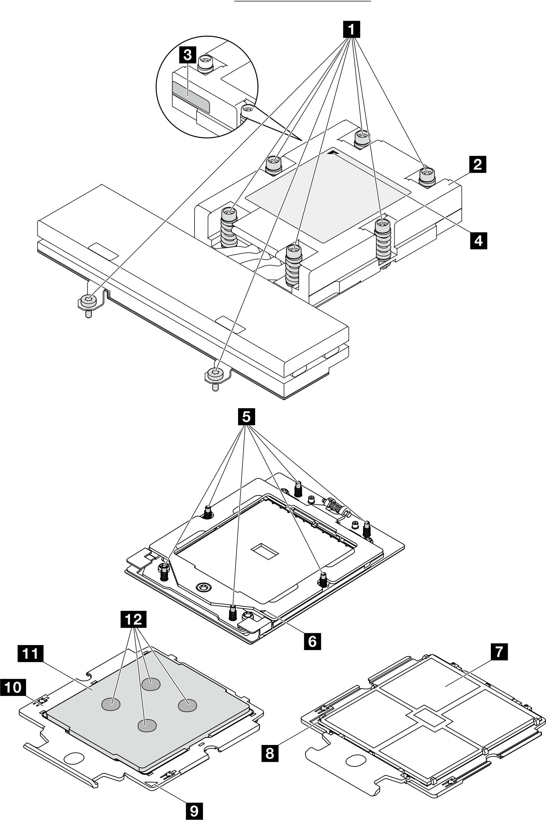
| 1 Captive screws | 7 Processor contacts |
| 2 Heat sink | 8 Processor triangular mark |
| 3 Processor identification label | 9 Carrier triangular mark |
| 4 Heat sink triangular mark | 10 Processor carrier |
| 5 Screw bolts | 11 Processor heat spreader |
| 6 Retention frame triangular mark | 12 Thermal grease |
Procedure
- Remove the heat sink.Note
Do not touch the contacts on the bottom of the processor.
Keep the processor socket clean from any object to prevent possible damages.
Figure 2. Removing a heat sink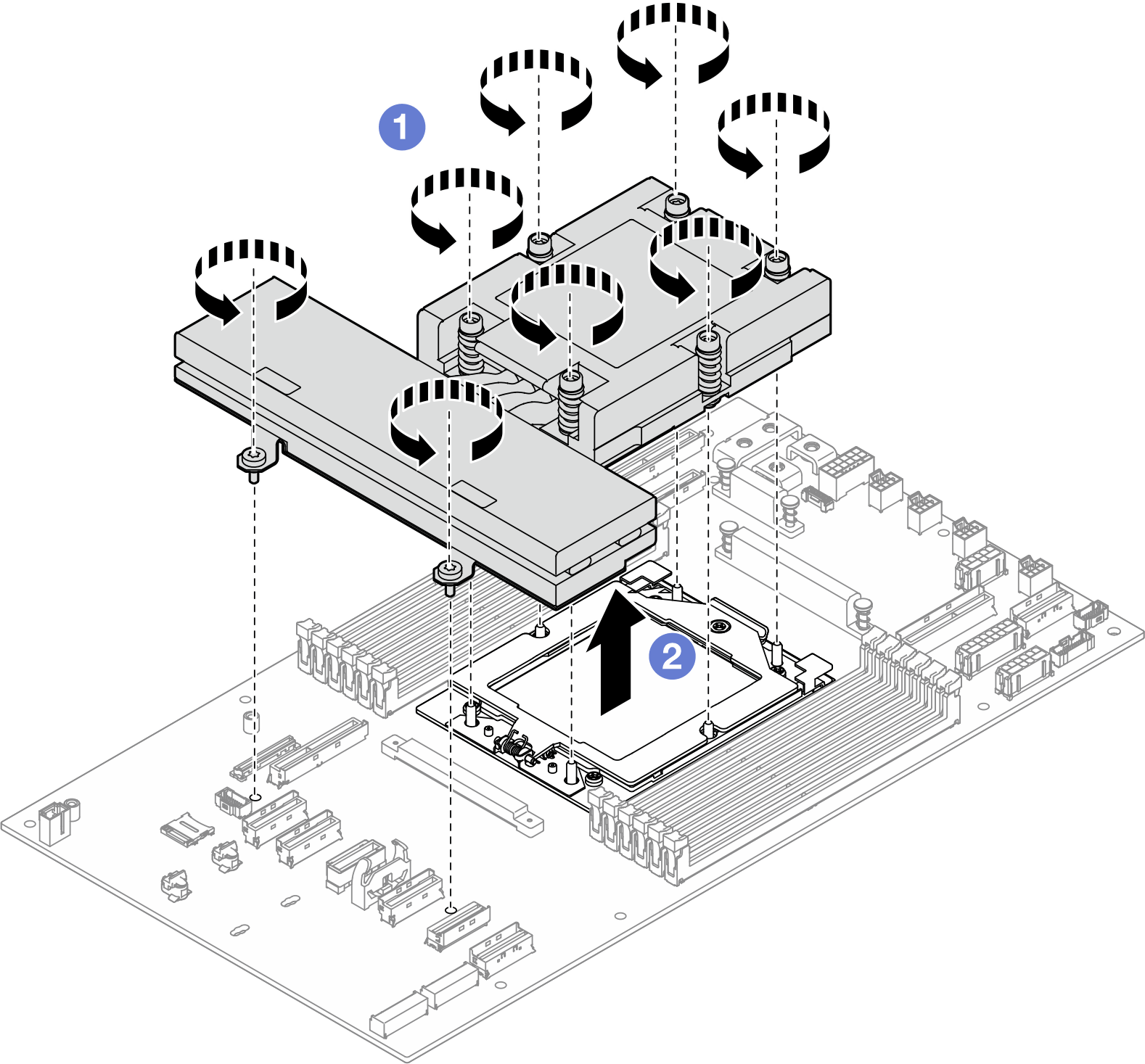
 Fully loosen all the screws on the heat sink in the removal sequence shown on the heat-sink label.
 Carefully lift the heat sink from the processor socket.
- Remove the processor.
- Use a Torx T20 screwdriver to loosen the screw.
- Slightly lift up the retention frame in the direction shown.
 Slightly lift up the rail frame in the direction shown. The processor in the rail frame is spring-loaded.
 Hold the blue tab of the processor carrier and slide the processor carrier out of the rail frame.
Figure 3. Removing a processor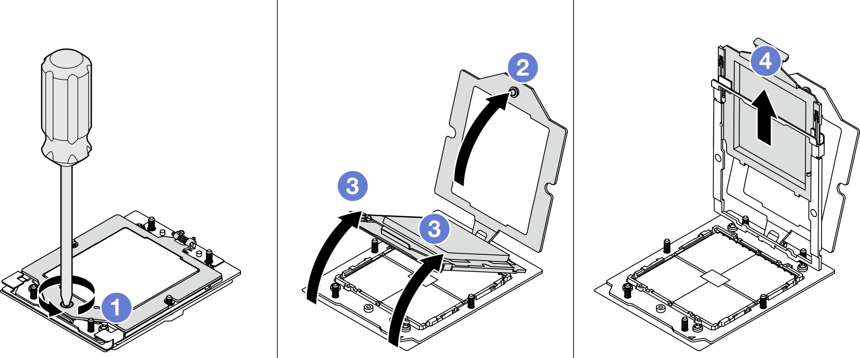
After you finish
- Install a replacement unit (see Install a processor and heat sink).
- If you are instructed to return the component or optional device, follow all packaging instructions, and use any packaging materials for shipping that are supplied to you.
Demo video
Give documentation feedback