Install a processor and heat sink
This task has instructions for installing a processor and heat sink. This task requires a Torx T20 driver. This procedure must be executed by a trained technician.
About this task
To avoid potential danger, make sure to read and follow the safety information.
Read Installation Guidelines and Safety inspection checklist to make sure that you work safely.
Prevent exposure to static electricity, which might lead to system halt and loss of data, by keeping static-sensitive components in their static-protective packages until installation, and handling these devices with an electrostatic-discharge wrist strap or other grounding system.
See Lenovo ServerProven website for a list of processors supported for your server. All processors on the system board assembly must have the same speed, number of cores, and frequency.
Before you install a new processor, update your system firmware to the latest level. See Update the firmware.
Go to Drivers and Software download website for ThinkSystem SD535 V3 to see the latest firmware and driver updates for your server.
Go to Update the firmware for more information on firmware updating tools.
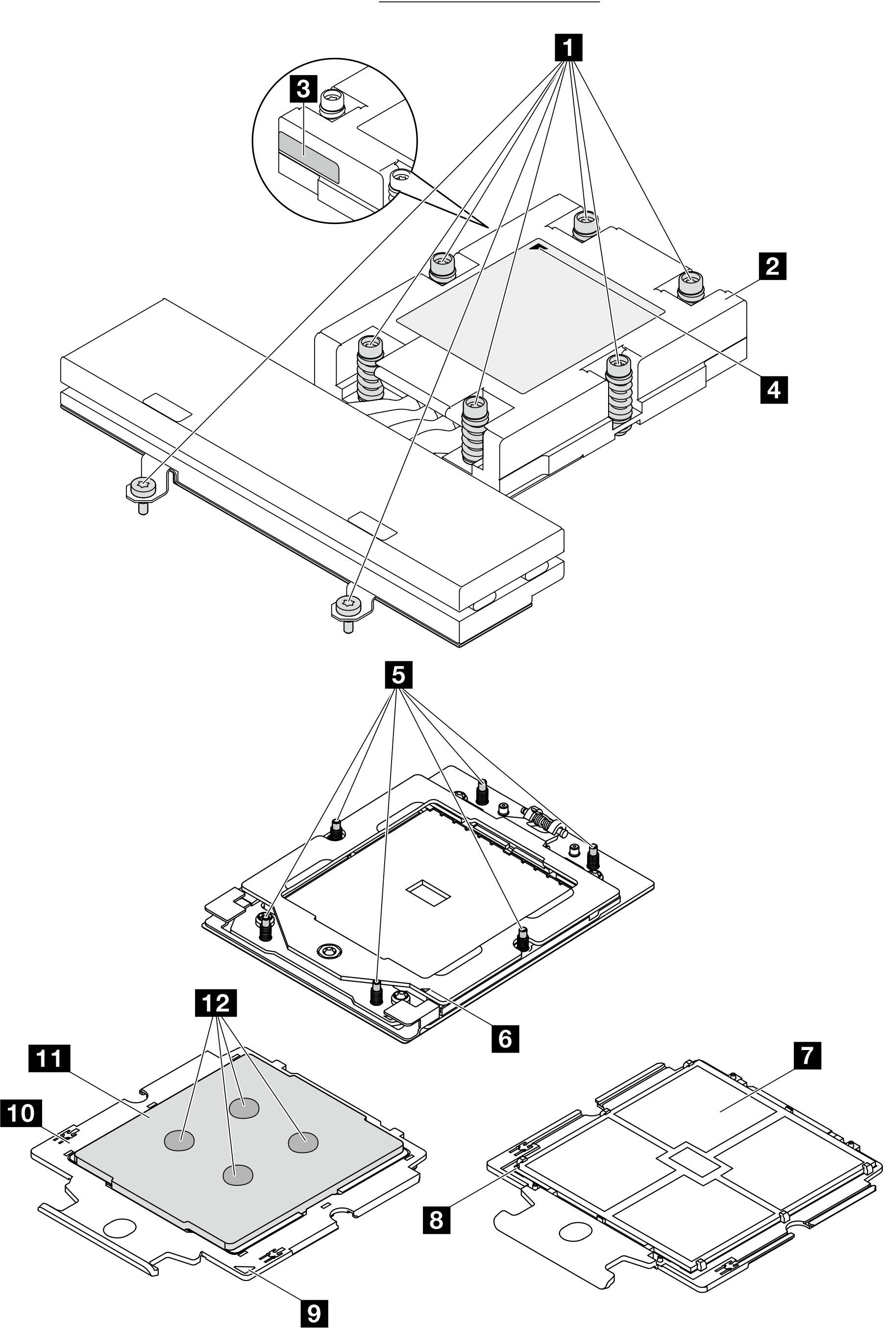
| 1 Captive screws | 7 Processor contacts |
| 2 Heat sink | 8 Processor triangular mark |
| 3 Processor identification label | 9 Carrier triangular mark |
| 4 Heat sink triangular mark | 10 Processor carrier |
| 5 Screw bolts | 11 Processor heat spreader |
| 6 Retention frame triangular mark | 12 Thermal grease |
Procedure
- Install the processor.
 Slide the processor carrier into the rail frame.
 Push the rail frame down until the blue latches lock into place.
 Close the retention frame.
 Use a Torx T20 screwdriver to tighten the screw.
Figure 2. Installing a processor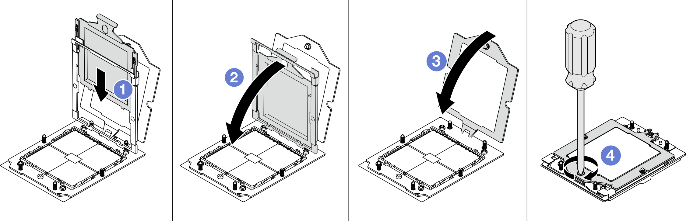
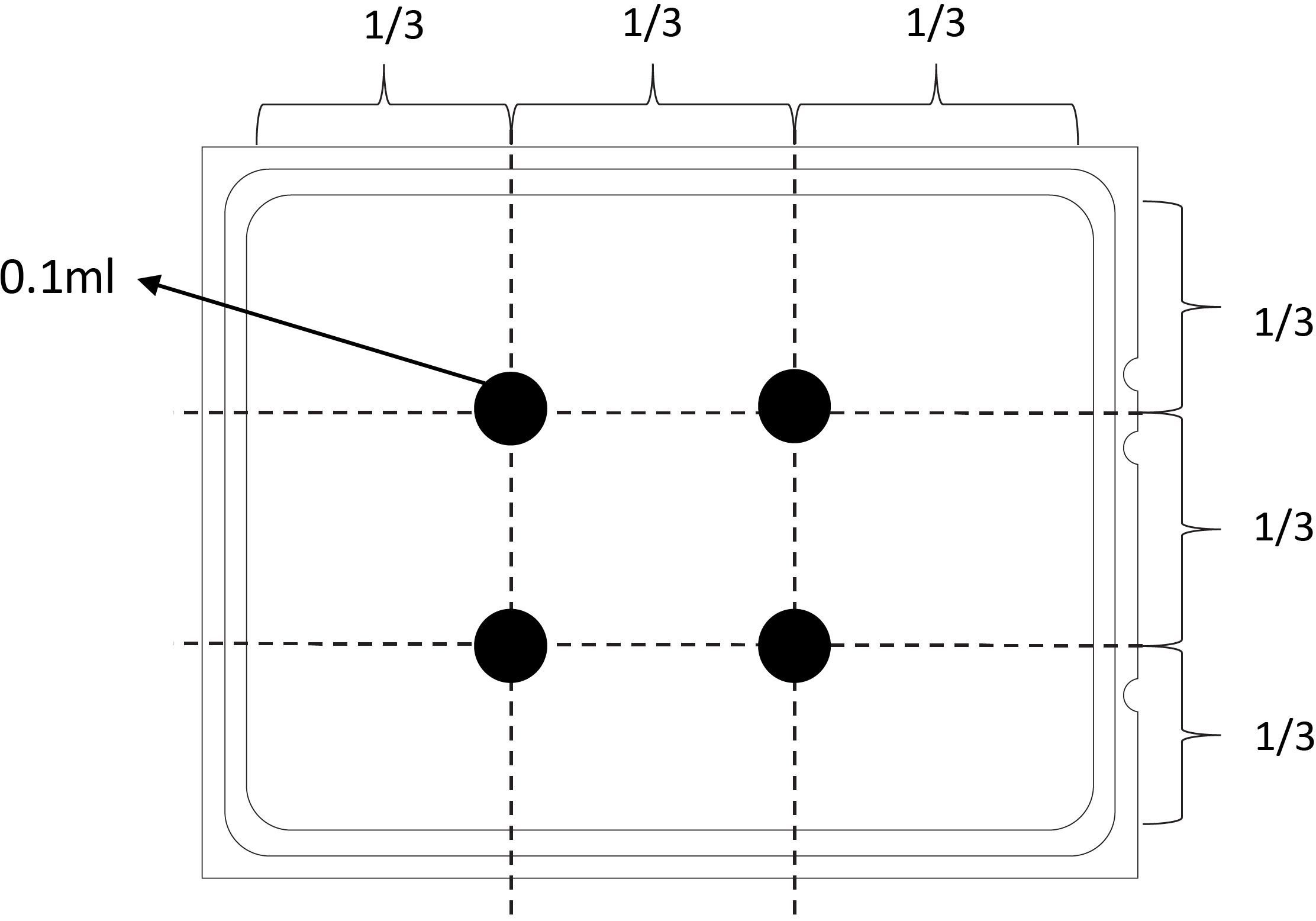
- Apply new thermal grease on the top of the processor with a syringe by forming four uniformly spaced dots, while each dot consists of about 0.1 ml of thermal grease.Figure 3. Applying thermal grease
- Install the heat sink.NoteFor reference, the torque required for the fasteners to fully tighten is 1.22-1.46 newton-meters (10.8-13.0 inch-pounds).Figure 4. Installing a heat sink
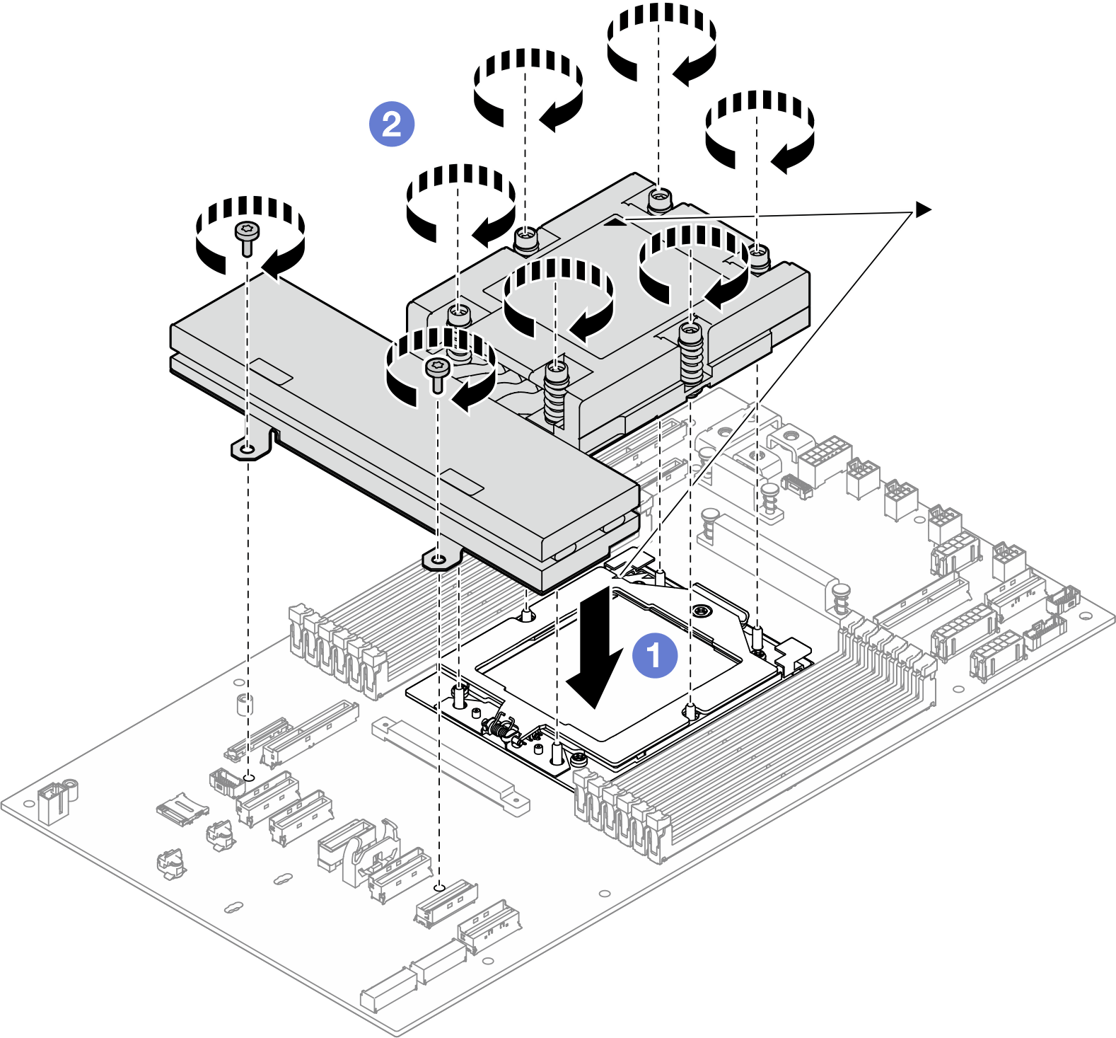
- Align the triangular mark and screws on the heat sink with the triangular mark and threaded posts on the processor socket; then install the heat sink on the processor socket.
- Fully tighten all the screws in the installation sequence shown on the heat-sink label.
After you finish
- Make sure that all the required cables are routed and connected correctly; then, reinstall the top cover (see Install the top cover).
- Reinstall the node into the chassis (see Install a node to the chassis).
- Make sure that the required power supply units are installed and power cords are connected; then, power on the node (see Install a hot-swap power supply and Power on the node).
- Proceed to complete the parts replacement (see Complete the parts replacement).
Demo video